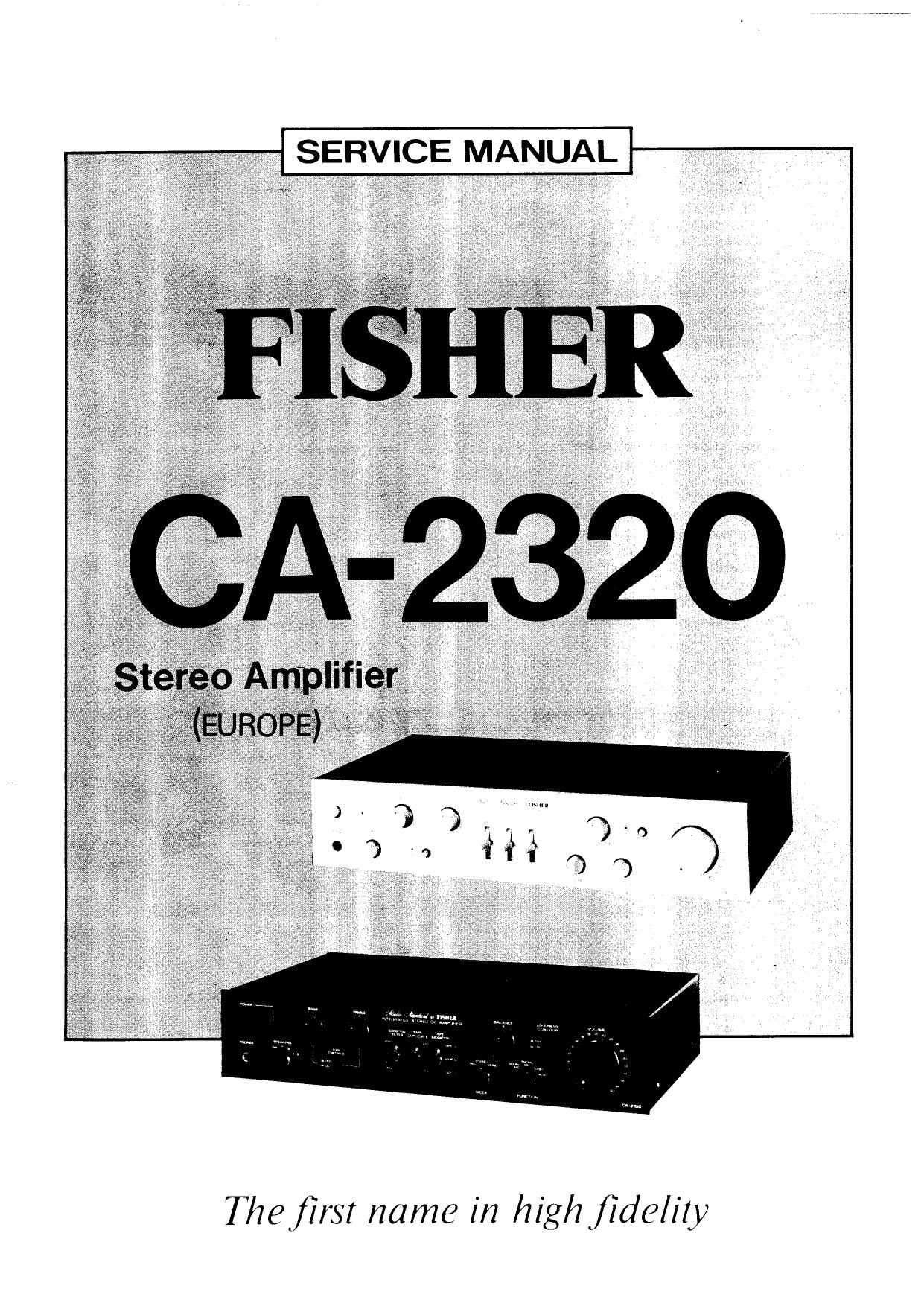
Fisher CA 2320 Service Manual

This is the 17 pages manual for Fisher CA 2320 Service Manual.
Read or download the pdf for free. If you want to contribute, please mail your pdfs to info@audioservicemanuals.com.

Page: 1 / 17
left right
Fisher CA 2320 Service Manual

Extracted text from Fisher CA 2320 Service Manual (Ocr-read)


Page 1

SERVICE MANUAL

'- in

Thefirst name in high fidelity

Page 2

CONTENTS

Functional Block Diagram ............................................. 2
Specifications ....................................................... 3
Tone Amp lC HA1457 Equivalent Circuit ...................................... 4
Power Amp IC STKOOGO Equivalent Circuit .................................... 4
Cabinet 8t Chassis Exploded View ........................................... 5
Parts List ........................................................... 6
Tone Switch P.ClBoard ................................................. 7
MC Head Amp P.CBoard ................................................ 7
Parts List ........................................................... 7
Speaker Switch P.C.Board ................................................ 8
Function P.C.Board .................................................... 8
Parts List ........................................................... 8
Power Switch P.C.Borad ................................................ 9
LED, P.CBOard ...................................................... 9
Tape Switch P.C.Board ................................................. 9
Parts List .......................................................... 9
Power Amp/Protector P.C.Board ........................................ 10
Power Amp/ Power Supply PtCBoard ....................................... 10
Parts List .......................................................... 1 l
Parts List (Continued) .................................................. 12
E0 Pre P.C.Board ................................................. 13,14
Recommended Test Equipment ............................................ 15
Adjustment of the Main Protect, Main Power P.C.Board ........................... 16
Explanation of Protective Circuits ......................................... 16
Point to Point Wiring Diagram ........................................... 17,18
Schematic Diagram .................................................. 19,20
Semiconductor Lead Identification ......................................... 21

FUNCTIONAL BLOCK DIAGRAM

HEADAMP

m: >-> .,
FUNCTlON sw
, , BALANCE VOLUME POWER AMP
so AMP rows AMP 51K 0060

i [ MOEINTOR M355 3 >4 _ SPE£>KERS
MM ,r%g >l +9 77%47»®7» 7 ~ *"t
, / g ,, , V
. 1 1 .

FUNER

AUX }
DUPLlCATE SW 1 LOUDNESS suasomc PHONES

, I

' V '7 V l

l

l

FILTER