Fisher 30 Service Manual 2

This is the 4 pages manual for Fisher 30 Service Manual 2.
Read or download the pdf for free. If you want to contribute, please mail your pdfs to info@audioservicemanuals.com.

Page: 1 / 4
left right
Fisher 30 Service Manual 2

Extracted text from Fisher 30 Service Manual 2 (Ocr-read)


Page 1

SERVICE MANUAL SUPPLEMENT

FM lAM TUNER 2083-5

Use t 3 supplement together with the 30, 35A, 50 Service Manual
for maintenance and repair of units using FM/AM Tuner 2083-5.

The Fisher

30 35A 50

WORLD LEADER IN HIGH QUALITY STEREO

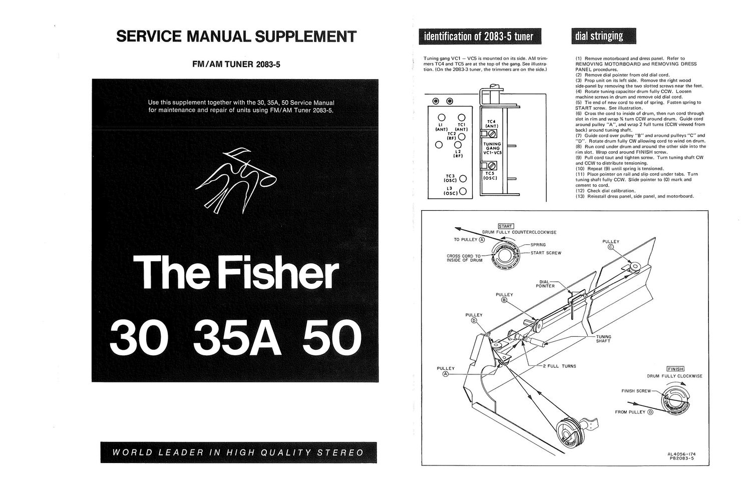
identififiation of 2083-5 tuner ,

Tuning gang VC1 - V05 is mounted on its side. AM trim-
mers TC4 and TC5 are at the top of the gang. See illustra-
tion. (On the 2083-3 tuner, the trimmers are on the side.)

has

O O m

u rcr (Am)
{:50 13%
O O =
£2 vcr'vcs

13%|

rcs
1c:
loscl 5 7"

L3
IOSC)

dials'trirgmg f,

lil Remove motorboard and dress panel, Refer to
REMOVING MOTORBOARD and REMOVING DRESS
PANEL procedures.

l2] Remove dial pointer from old dial cord.

(3) Prop unit on its left side. Remove the right wood
side-panel by removing the two slotted screws near the feet.
(4) Rotate tuning capacitor drum fully CCW. Loosen
machine screws in drum and remove old dial cord.

(5) Tie end of new card to end of spring. Fasten spring to
START screw. See illustration.

(6) Cross the cord to inside of drum, then run cord through
slot in rim and wrap /A turn CCW around drum. Guide cord
around pulley "A", and wrap 2 full turns lCCW viewed from
back) around tuning shaft.

(7) Guide cord over pulley B" and around pulleys "C" and
D". Rotate drum fully CW allowing cord to wind on drum.
(8} Run cord under drum and around the other side into the
rim slot. Wrap cord around FlNlSH screw.

(Bl Pull cord taut and tighten screw. Turn tuning shaft CW
and CCW to distribute tensioning.

(10) Repeat (9) until spring is tensioned.

(11) Place pointer on rail and slip cord under tabs. Turn
tuning shaft fully CCW. Slide pointer to (0) mark and
cement to cord,

(12) Check dial calibration,

(13) Reinstall dress panel, side panel, and motorboard.


To PULLEY (/9
$3055 cone T0 g;
l SIDE OF DRUM I: j?

v

PULLEY

PULLEY

PULLEY

DRUM FULLY COUNTERCLOCKWISE

Mar-Rim;
\
~/,,,© \\ START scnew

DIAL
POINTER

PULLEY

TUNING
SHAFT

DRUM FULLY CLOCKWISE

FlNlSH SCREW

FROM PULLEY ®

AL4056-l74
P82083-5

Page 2

Turn TUNING knob fully CCW. If pointer is not centered on (0),
reposition and cement pointer, Except as noted, maintain generator level
3* as low as possible during alignment.

FM ALIGNMENT

(1) Set SELECTOR switch to FM. Turn VOLUME control to minimum.
Connect jumper between P3 and P4 to defeat AFC.
(2) Connect 10.7MHz sweep generator to P29. Connect scope through
220K to P28. Open wire loop at P24.
(3) Detune top core of L9. Adjust top and bottom cores of L8, L7,
and L6, and bottom core of L9 for maximum gain and symmetry.
(4) Reconnect wire loop at P24. Reconnect scope to P5. Adjust top and
bottom cores of L9 for maximum linear amplitude.
(5) Set sweep generator for CW output at 10.7MH2. Connect DC
VTVM to P5. Readjust top core of L9 for OVDC. Disconnect sweep
generator and DC VTVM and connect scope to RCDR OUT jack. Con-
nect FM RF generator through 120-ohm carbon composition resistors
to FM ANT. terminals.
(6) Set generator frequency and dial pointer accurately to 90MHz.
Modulate generator with 400 Hz, t75kHz deviation. Adjust core of
antenna coil L1 and bend oscillator coil L3 and RF coil L2 for max»
imum amplitude on scope.
(7) Set generator frequency and dial pointer accurately to 106MHz.
Adjust antenna trimmer TCl, oscillator trimmer TC3, and RF trimmer
TC2 for maximum amplitude on scope.
(8) Repeat (6) and (7) for maximum sensitivity and accurate dial
calibration. Disconnect scope.
(9) Reconnect DC VTVM to P5.Set generator level to 1mV. Tune
receiver to generator frequency (106MHz) for OVDC at PS.
(10) Connect an AC VTVM to the RIGHT RCDR OUT jack, and another
AC VTVM to the LEFT RCDR OUT jack.
(11) Connect MPX generator composite output to FM generator
EXTERNAL MODULATION input. Modulate left and right channels
with 400Hz (167.5kHz deviation/90%), and 19kl~lz pilot (:7.5kHz
deviation/10%).
(12) Adjust top cores of L17 and L18 for maximum audio.

© DENOTES PARTS MOUNTED 0" UNDERSIDE OF BOARD AL2083- HZ A (13) Modulate left channel only. Right channel AC VTVM should
indicate at least ZOdB below left channel output.
(14) Modulate right channel only. Left channel AC VTVM should
indicate at least ZOdB below right channel output.
(15) Disconnect MPX generator. Set RF generator output to 20mV, and
modulate with 400Hz, :75kHz deviation.

f (16) Detune generator frequency for +0.5VDC at P5. Disconnect jumper

between P3 and P4 to turn AFC on. DC VTVM should indicate OVDC
1200mV.

OPEN WIRE
LOOP DURING l0.7MHt
l-FM IF ALIGNMENT SWEEP
._-_ _ J - (17) Reconnect jumper between P3 and P4 and detune generator for

P29©/ P2© @P. --0.5VDC at P5. Remove jumper. Meter should indicate OVDC tZOOmV.
0 p5 t 3 Disconnect test equipment.
220K ©P24 p4

r 0 Q m AM ALIGNMENT
LI TC
(IQKHI) ©

I
O (ANT) (ANT) (ANT) meet SELECTOR switch toAM. Turn VOLUME control to minimum.
2 T02. B®l (2) Connect 45§kHz sweep generator through 0,1uF to P19. Connect
3 (RF)
2' © 0
0


rs
l

scope through 220K to P6,
=TUNING (3) Adjust cores of L14, L13, L11,and L10 for maximum gain and
L2 GANG symmetry.
(RF) VCl-VCS (4) Disconnect sweep generator. Connect AM signal generator through
D@ I 220pF to P19. Connect scope and AC VTVM to RIGHT RCDR OUT
jack.

Tcs . TC5 (5) Set generator frequency and dial pointer accurately to BOOKHZ.
(039) (056) = Modulate generator with 400Hz, 30% modulation. Connect a short
053 L3 . jumper between P21 and chassis. Adjust oscillator coil L12 for maximum

(05C)

amplitude.
é JUMPER
0 O

(6) Set generator frequency and dial pointer accurately to i400kHz.
Pls PZI 0

L6
IQIMHI)

(Left-ix) 0 O
r a (at...) (9
L 1 ©

Le
us © ® l0.7MH
(38km) p23 0 ( I)

© © 220K © HBO

L1! L20 Oezo
H (455nm (455nm)
\ YEL RED _

FM

\

3.4

Adjust oscillator trimmer TCE for maximum amplitude.

(7) Repeat (5) and (6) for accurate dial calibration and maximum gain.

(8! Disconnect jumper connection P21. and chassis. Reconnect AM signal

l LIZ (05C) generator to AM ANT. terminal. Open GND link. Tune receiver to

generator frequency at 600kHz. ModUIate generator with 400Hz, 30%

4551011 . .

L/aluF SWEEP modulation. . . . .
\_ AM RF (9) Melt the wax holding the cowl to the ferrite antenna. Shift the (20)) for

ZZOpF maximum audio indication. To secure coil in position, remelt wax.
(10) Tune receiver to generator frequency at 1400kHz. Adjust antenna
ALZOalrl77 trimmer TC4 for maximum audio.

i
z
i
X
E
z
x
i
i
g