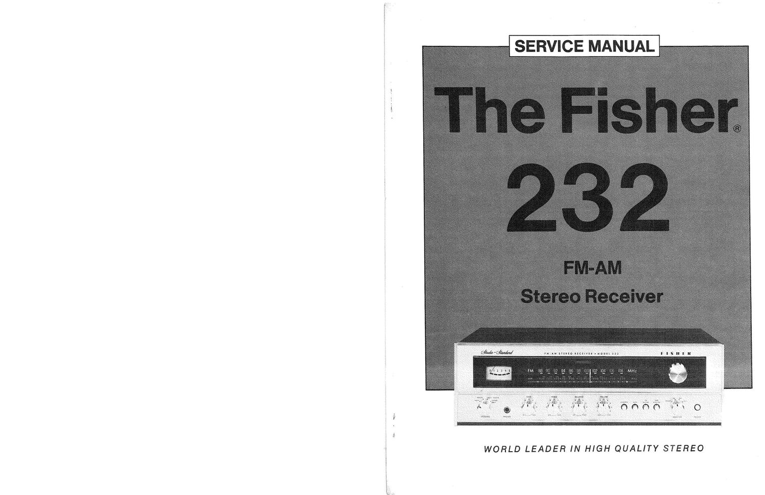
Fisher 232 Service Manual

This is the 10 pages manual for Fisher 232 Service Manual.
Read or download the pdf for free. If you want to contribute, please mail your pdfs to info@audioservicemanuals.com.

Page: 1 / 10
left right
Fisher 232 Service Manual

Extracted text from Fisher 232 Service Manual (Ocr-read)


Page 2

i
i
i
l

CAUTI ON. This precision high-fidelity instrument should be serviced only by qualified
I personnel, trained in the repair of transitorized equipment and printed circuitry.

ALIGNMENT

REQUIRED EQUIPMENT

0 Line Voltage Autotransformer or Voltage Regulator 0 Two (2) Load Resistors, 8sohms,

- AC DC Multimeter 50 Watts (Minimum Rating)

a Accurately Calibrated AC Voltmeter Low~Distortion AM-FM Signal Generator
0 Oscilloscope (Flat to lOOkHz Minimum) ' 10-7 MHZ Sweep»Generator

0 Low-Distortion Audio Sine-Wave Generator ' Multiplex Generator

' Harmonic Distortion Analyzer ' 455KHZ Sweep Generator

\ FM-TUNER ALIGNMENT

FM MUTING OFF, TONE CONTROLS and BALANCE to center, SPEAKERS
Switch to PHONES, MODE to STEREO, SELECTOR to FM, VOLUME to MIN, TAPE MONITOR OFF.

Maintain generator output as low as possible for suitable indication.

ITEM GENERATOR DIAL SETTING INDICATOR PROCEDURE

Note: The PM lF circuit utilizes a non-tunable ceramic filter which establishes the IF bandpass. To insure symmetrical
tuning and selectivity, the IF must be aligned precisely to the center of the filter bandpass, rather than to 10.7 IVIHZ as
in conventional LC circuits.

1. IF Connect 10.7 MHz Position of non- Scope vertical input Short FM oscillator variable
ALIGNMENT Sweep Generator to interference. to TP2 (FM OUT). capacitor (section nearest
TPl (FM IN). Ground lead to rear L4) with a clip lead as shown
Markers are not required. of chassis. in alignment layout. Detune
T9 by turning core up
(CCW).

Adiust T5, T3, T2, T1 for
curve as shown in FIG. 1.
Repeat as required to ob-
tain best shape.

Adjust T9 for best shape
(widest bandpass, not for
max amplitude).

2. PRELIMINA- Reduce output ampli- Connect scope Adjust T7 top and bottom
RY DETECT- tude as much as pos- vert input to TP3 for best gain and symmetry.
0R ALIGN- sible throughout (DISCRI). S-curve should appear
MENT this procedure. as shown in FIG. 2.

NOTE: l20-ohm composition resistors in series with each lead from the RF generator match the 50-ohm output to
the SOC-ohm input impedance. Generator output voltage is reduced to one~half at antenna terminals. Signal voltages
specified in this table are generator output levels, not antenna voltages.

3. FRONT END Tuning knob fully Center dial pointer on 0
ALIGNMENT CCW. and cement it in place.

© COPYRIGHT 1975 FISHER RADIO 0 All Rights Reserved.