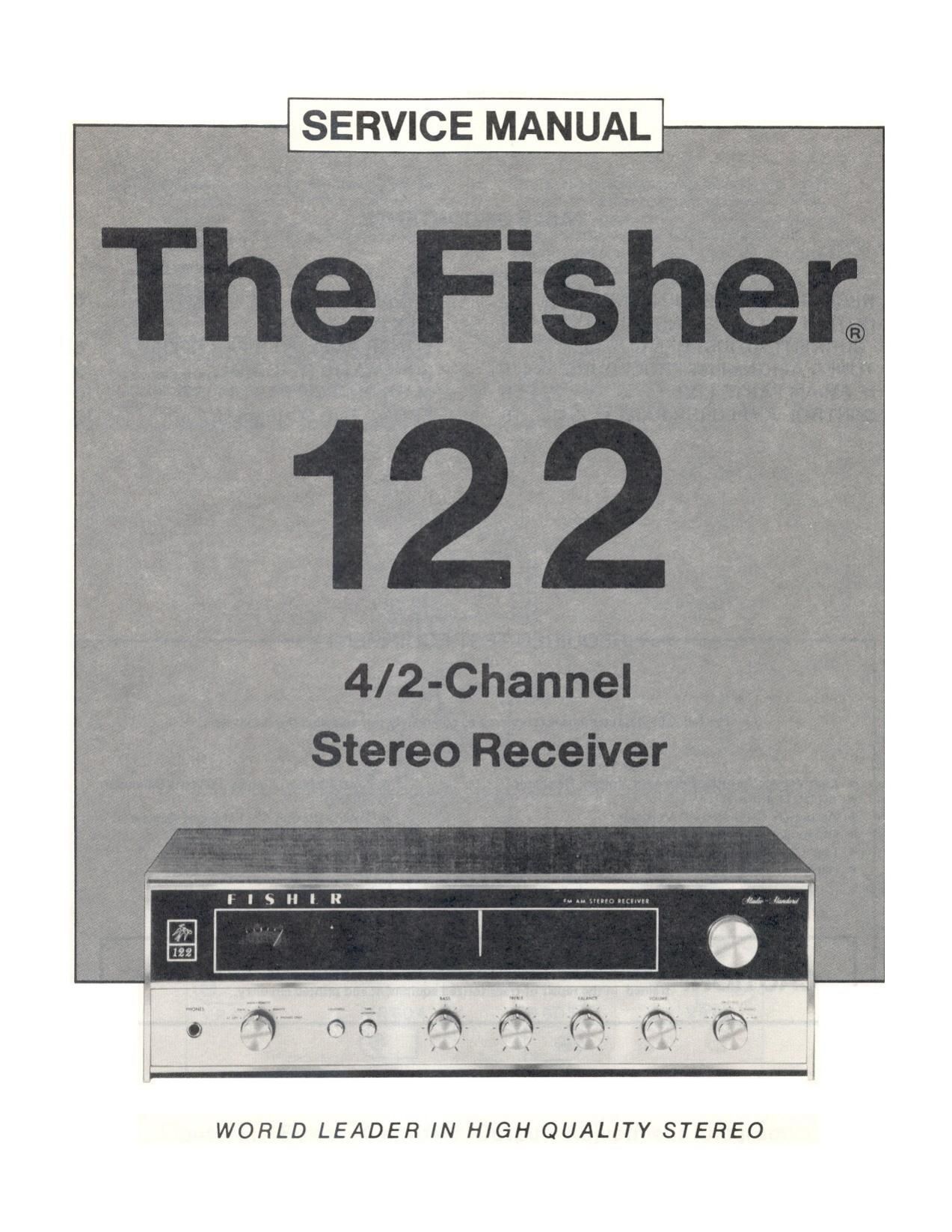
Fisher 122 Service Manual

This is the 18 pages manual for Fisher 122 Service Manual.
Read or download the pdf for free. If you want to contribute, please mail your pdfs to info@audioservicemanuals.com.

Page: 1 / 18
left right
Fisher 122 Service Manual

Extracted text from Fisher 122 Service Manual (Ocr-read)


Page 1

SERVICE MANUAL

)- _
XW'
l l s H l I!

WORLD LEADER IN HIGH QUALITY STEREO

Page 2

TABLE OF CONTENTS

REQUIRED TEST EQUIPMENT 2 PREAMPLIFIER PARTS LIST
OUTPUT BALANCE AND IDLE 3 MPX PARTS LIST

CURRENT ADJUSTMENT
TUNER ALIGNMENT PROCEDURE 4,
IF FM-AM PARTS LIST
CONTROL AMPLIFIER PARTS LIST

POWER AMPLIFIER PARTS LIST
5 SCHEMATIC DIAGRAM
5 MAIN CHASSIS PARTS LIST
6 FRONT END SCHEMATIC

REQUIRED TEST EQUIPMENT

The following test equipment is required to completely test and align the Receiver:

Line Voltage Autotransformer or Voltage Regulator Load Resistor, B-ohms, 20 Watts (Minimum
AC DC Multimeter Rating)

Accurately Calibrated AC Voltmeter Low-Distortion AM-FM Signal Generator
Oscilloscope (Flat to 100 kHz Minimum) 10.7 MHz Sweep Generator

Low-Distortion Audio Sine-Wave Generator Multiplex Generator

Harmonic Distortion Analyzer 455 kHz Sweep Generator

-I-l

OOLDGJNO)

CAUTION. This precision high-fidelity instrument should be serviced only by qualified personnel,
' trained in the repair of transitorized equipment and printed circuitry.