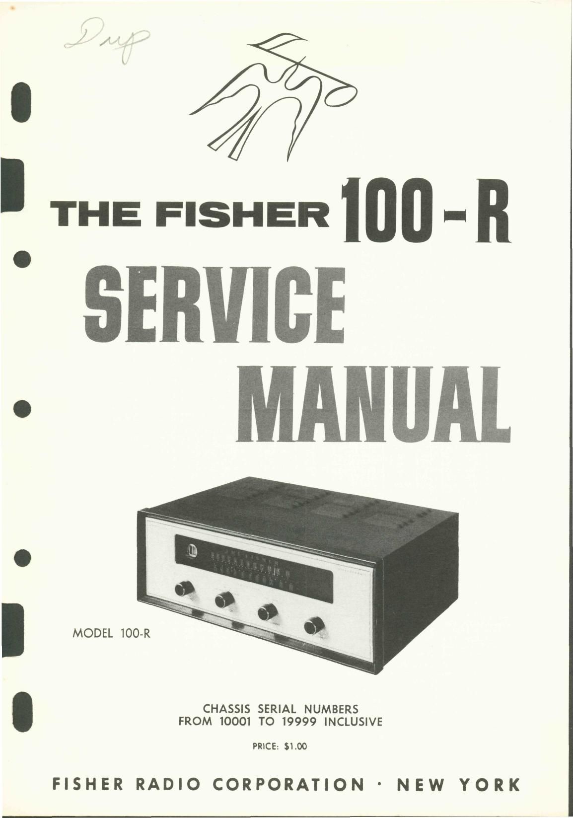
Fisher 100 R Service Manual

This is the 5 pages manual for Fisher 100 R Service Manual.
Read or download the pdf for free. If you want to contribute, please mail your pdfs to info@audioservicemanuals.com.

Page: 1 / 5
left right
Fisher 100 R Service Manual

Extracted text from Fisher 100 R Service Manual (Ocr-read)


Page 1

I THE F.5HER mu .. n

SERVICE

MODEL 100-R

CHASSIS SERIAL NUMBERS
FROM 10001 TO 19999 INCLUSIVE

PRICE: $1.00

FISHER RADIO CORPORATION ' NEW YORK

Page 4

CHASSIS: Turn the station selectors completely counterclockwise, wtthaut forcing, Dial pomters
If not, reset the dial painters,
external antennas and the antenna link. Set Ferrite Loop to normal position, parallel to rear panel.
When using an oscilloscope for alignment, set the output level controls for no overload, as shown

should be at zero index mark on Iogglng scale

by the proper waveform shape,

SIGNAL GENERATORS: The signal generator equipment must be able to supply the followlng:
FM RF modulated 30% (122.5 KC deviotlunl a? 400 cps; AM RF modulated 30% at 400 cps;

ALIGNMENT INSTRUCTIONS

Read These Instructions With Extreme Care Before Attempting Alignment.

Dlsconnect the

AM 1F wtth JOKC sweep for AM bandwidth adiustment.
INDICATOR: DC VTVM, AC VTVM, and scope for allgnmettt.
filter adjustment.

ALIGNMENT: Allow the chassis and test instruments to warm up tor at least fifteen minutes,

AC VTVM tar IO KC AM whistle

Adiust the line voltage for 117 volts AC, 5060 cycles, Use fully insulated tools; a small screw-

driver tor all trimming capacttors; a K~Tran tool tor 2l, 22, 25, 26 and 27; a hex tool for 23,
24, L1, L8 and L9. For AM alignment, short test point AVC to ground.

cmlssts SIGNAL GENERAYOR INDICAYOR ALIGNMENT
STEPS
AM SElECTOR OUPLING FRE , v
BANDWIWH SELECTOR MON 6 Q MOD T PE CONNECTION ADJUST INDICATION
. , AM Gen connected rtuu . 26 27
Point or no stgnoI . so /. AM at AC VTVM to ctr. A -
l SHARP AM _ .0l.ut cap, in Serles With not 455 KC to a a M ' lr
AM ALIG N M E N T and no intertorone lead m v7, Pm 7 400 cm Output ham? flxmum W was
Pom at "a signal AM Gen. _cannected thru 30 KC Scope to Ch. A 26 AdlusI slightly tar
2 BROAD AM and no tntertoronco vOV-Uflgggr'g;;f';§nw7nh hot 455 KC sweep Output Bottom symmetrical curve
AMfGen. connortod tntu
220-uu cup ln setles with hat soy. AM at Ac VTVM to Ch A llz, 25 .
3 SHARP AM 60° KC lead to antenna torrninal A 50° KC 400 (ps Output L2 M"' V°"°9e
Disconned link between A A. 5
AMfGen connorteo thru
zzo-uu cap, in sales with ha) ,4 :07. AM at Ac VTVM to ch, A CIE, c2c, .
SHARP AM 00 KC lead to antenna terminal A 00 KC Aoo cps Output C24 M°x"" V°I'°9
Disconnect link between A r. 5
5 Repeat steps a and 4 tor otooer dial calibtalion and maximum output.
Pair" of no signal FM Gen. connected ta 21: 2% Z3 Maximum negative
5 TM f ungraundod lube to 7 MC None DC VTVM to test point 2 and 24, top
d "° ""e' 2" shield at v2 at bottom W9
Potnt at no signal FM GE". waned 0 Connect VT VM Zero readirt on zero
7 FM and no intertorenre "9'?"d-d 79 0 7 MC we to test point 3 Z '09 center 59:an
FM ALIGNMENT "°
FM. Gin. :anne:ted_thru _ 30% FM DC VTVM to the iunction LE L7 Check for sine waveform
3 FM 90 m: M" 70- m "50" mm In 90 MC 122.5 KC not.) at R32 and R25 onrl scope on; L3 and udlust tor maximum
sew W '9 0 memo (1)400 cps to Cl», A. Output negative vallage
teimlnals 4 and 5
FM. Sher» connectedfhm , 307. FM DC VTVM to the iunctlcn as c, Check for sine waxetatrn
9 FM 106 Mc 'W° 0" I" clu'lm "35'5 1" 106 MC (225 KC Dev.) or R32 and R25 and scope my co and udiust tor maximum
SET-es Wl'? sod '0 Wanna at 400 cps to Ch. A. Output negative voltage
terminals A and s
to Repeat steps a and q tor proper LItal callbrm'lon and maximum output.

NOTE: For mllbrming both the AM and FM, use as low on output voltage as posstble from your signal generator.