Ferrograph Y 724 Service Manual

This is the 74 pages manual for Ferrograph Y 724 Service Manual.
Read or download the pdf for free. If you want to contribute, please mail your pdfs to info@audioservicemanuals.com.

Page: 1 / 74
left right
Ferrograph Y 724 Service Manual

Extracted text from Ferrograph Y 724 Service Manual (Ocr-read)


Page 1

Y722
Y722"
Y722L
TIZ
Y72lL

FERROGRAPH

SERIES SEVEN SECTION1

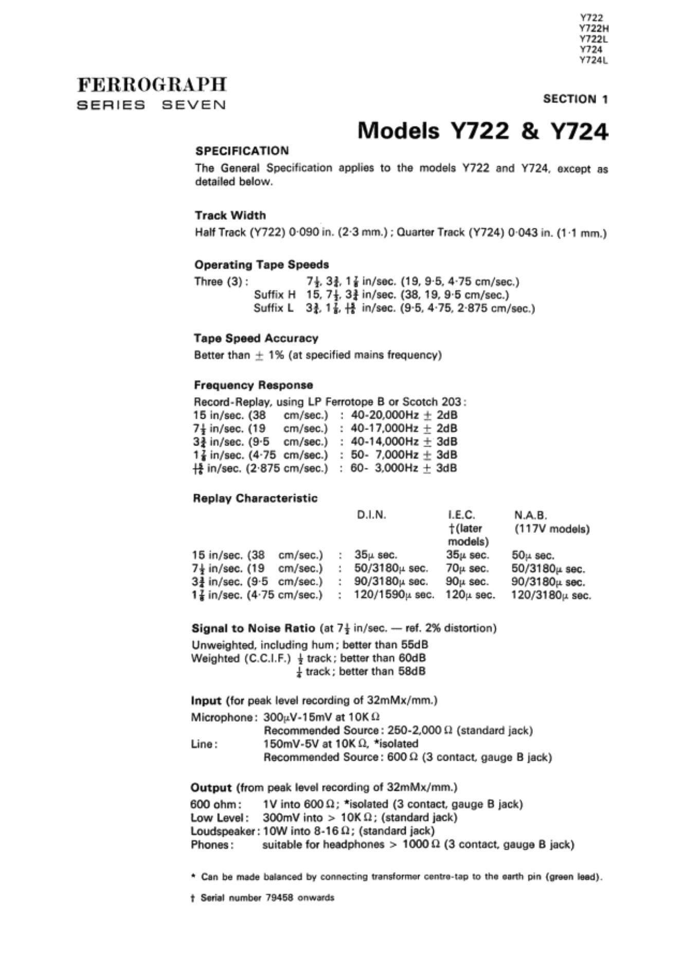
Models Y722 & Y724
SPECIFICATION

The General Specification applies to the models Y722 and Y724, except as
detailed below.

Track Width
Hail Track (Y722) 0090 in. (2-3 mm.) ; Quarter Truck (Y724) 0-043 in. (1 1 mm.)

Operating Tape Speede

Three (3): 7*. 3i, 1iln/sec. (19, 95. 4-75 cm/sac.)
Suffix H 15. 7f. 3} in/eec. (38. 19, 9-5 cm/sec.)
Suiiix L 3!, ii. {if ln/eec. (9'5. 475, 2-875 cm/aeo)

Tape Speed Accuracy
Better than 1 1% (at specified mains frequency)

Frequency Reeponee

Reoord- Replay. using LP Forrotope B or Scotch 203:

15 in/sec. (38 cm/eec.) : 40- 20000Hz + 2113
7iin/eec. (19 cm/eec.) : 40-17000Hz 1- 2d8

3! in/aec. (9'5 cm/aec.) : 40-14,000Hz 1 ads

1} in/eec. (4.75 cm/eec.) : 60- 7.00011: t 3d8

H in/eec. (2.875 cm/sec.) : 60- 3.000112 1: 3dB

Replay Characteristic

D.|.N. LEC. N.A.B.
later (117V models)
models)
15 in/sac. (38 cm/eeo) : 35;: sec. 35.- eec. 50;: sec.

7} him. (19 cm/eec.) : 50/3pr sac. 70p. aec. 50/3180p aec.
3} in/sec. (9~5 cm/sec.) : 90/3180» sec. 90p sec. 90/3180p sec.
1 in/oec. (4-75 cmleec.) : 120/1590p sec. 120p. sec. 120/3180 sec.

Signal to Nolae Ratio (at 7* in/aao - ref. 2% distortion)

Unweiphted. including hum; better than 55dB
Weighted (C.C.I.F.) (track; betterthan 60dB
* track; better than 6MB

Input (for peak level recording of 32me/mm.)
Microphone: 300pV-15mv at 10K i)

Recommended Source: 260-1000 11 (standard jack)
Line: 150mV-6V at 10K 0. isolated

Recommended Source: 6000 (3 contact. gauge B lack)

Output (from peak level recording oi 32me/mm.)

600 ohm: 1V into 6009; 'iaoieted (3 contact. gauge B jack)

Low Level: 300mV into > 101}; (standard jock)

Loudspeaker: 10W into 8-160: (standard jock)

Phones: suitable for headphones > 1000 Q (3 contact. gauge 8 jack)

Can be made nuanced Irv connecting tranalormer oermatep to the eerth pin (ween teed).
t Seriel number 19458 onwards

Page 2

FIG. 1. EXPLODED VIEW OF TAPE-DECK (PARTS LIST IDENTIFICATION)

Page 21

FERROGRAPH

SERIES SEVEN

Model Tape Spud Tape Spud
No. System Track III/Sec Cm/Sec
722 Stereo Hall 7*. 3L 1 19. 9-5, Han track stereo
4-75 mm with 10 watt
722M Stereo Ha 15. 7}, 3! 38. 19, 9-6 output on each
chamol. A transfer
switch is fired for
tpocial effects.
724 Stono Quarter 7}. 3}. 1} 19. 9-5, Ouamr track version
4-75 01 722.

10

Page 26

FERROGRAPH

SERIES SEVEN

116

117

113

119

120

due to the tape tension and power is dissipated in the form of heat. By moving
slider RV103 to either side of the central position. the power is divided unequally
between real motors. so that tape wind is achieved in either direction at slow or

fastspeeds.

Switch SW100 poles. to and 2b, are connected via Pl 00/SK100 to the amplifier
unit so that in the Fast position the level of the audio output. caused
by the tape passing the replay head at high speed. is reduced.

Function Control at Stop (Figs. 8. 27 and 28)

With function control SW100 at Stop. the cam sets the constant friction brake
arm so that the constant Motion brake is Just clear of the supply reel drum. end a
pin on the cam sets the loading arm so that the pressure pads are approximately
i in. (9-5 mm.) from the heads.

Electrical switch SWIOOisat positionSas shown in Figs. 27 and 28. Poieel bandt c
disconnect the Fest Wind potentiometer from across the reel motors. and poles
1a and 2b, via MOO/5K1 00. reduce the audio output level of the replay boards.
Pole 2a of the switch disconnects the supply to solenoid L100 which is de-
energised and the start lever is in the non-operating position. With the start
lever in this position the following conditions apply:

(i) The wrap-round brakes are applied to the reel drums.

(ii) The selected idler wheel is dbengeged from the capstan motor pulley and
flywheel.

(iii) Micro-switches SW102 and SW103 m not operated. With micro-switch
SWIOZ in its non-operated position. the supply to the capstan and reel
motors, lrom P101, is disconnected. On later models. when SW103 is
in its non-operated position. the 24 volt d.c. supply to the run solenoid
L100 is also disconnected.

Function Control at Peuee (Figs 8. 27 and 28)

With the function control SW1 00 at its Pause position. the constant friction brake
arm. actuated by a brake arrn spring. pulls the constant friction brake into contact
with the supply reel drum. The vertical pin on the cam no longer acts on the
loading arm. which. actuated by a return spring, allows the pressure pads to
function. and moves the pinch roller arm. The pinch roller arm is moved by a
plastic ramp on the loading arm acting on the pinch roller bracket. so that the
armature on the pinch roller bracket is in close proximity with the run solenoid

pole piece.

Electrical switch SW100 is at position P as shown in Figs. 27 and 28. Pole 2a
completes the circuit of start solenoid L100 and the solenoid is energised. As
the armature is pulled to the pole piece, the start lever moves about its pivot and
perlorrns the following lunctions:

(i) Self-wrapping brakes are released from the reel drums.

(ii) The leaf spring. on the start lever extension. moves the selected idler wheel
into engagement with the capstan motor pulley and flywheel.

(iii) Two arms, on the start lever rear bracket. operate micro-switches SW102
and SW103, energising the capstan and reel motors.

15

Page 54

FERROGrRAPII
SERIES SEVEN

SECTION 4

Test Procedures and Adjustments

CO "TENTS A.

Pmnph

MECHANICAL
General 401-402
Solenoids. Micro-twitches. Motors and Brakes 403
Counter Mechaniem 404
Idlers end Idler Arms 406
Run Solenoid and Pinch Roller Arm
Loading Arm and Preseure Arms 407
Cut-Out Switches and Damping Arms 408
Tape Transport 409
Cepsran and Fiywlieel 410
Friction Brake 411
Record Button 412
Main Function Switch and Lock Lever 413
Tape Speed Using Measured Tape or

Stroboccopic Tape 414
Wow and Flutter Measurement 415
ELECT RONlC
General 416-418
Equipment Required 419
Replay Heed Alignment 420
Replay Frequency Response 421
Replay Response Correction 422
Replay Output Level 423-424
Mic and Line Input: 425
Record Heed Alignment 428
H.F. Bios Setting 427

Record/Replay Frequency Response Measurement 428
Record/Replay Frequency Response Correction 429

Record Heed Mutiny 430
Noise Level Measurement 431
Noise Level Carnation 432
Distortion Measurement 433
Causes of Excessive Distortion 434
Erasure 436
Crosstalk 436
Replay Amplifier 437
Loudspeaker Output 438
Power Amplifier 439

49