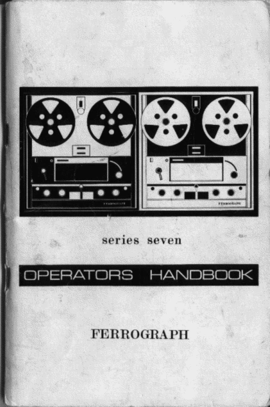
Ferrograph 724 Service Manual

This is the 40 pages manual for Ferrograph 724 Service Manual.
Read or download the pdf for free. If you want to contribute, please mail your pdfs to info@audioservicemanuals.com.

Page: 1 / 40
left right
Ferrograph 724 Service Manual

Extracted text from Ferrograph 724 Service Manual (Ocr-read)


Page 1

series seven

L OPERATORS HANDBOOK

FEHROGRAPH

Page 2

MID-ODD. ISSUE 4

OPERATOR'S HANDBOOK

Farragmph

SERIES SEVEN. MK 2

SEFIIAL NUMBER 78.800/2 ONWAHDB

THE FERROGRAPH COMPANY LID.
IONDON AND SOUTH SHIELDS

Page 12

knob to "Stop". It has no effect ll presead on "Stop" or Fast". nor
wrll rt lock down with the Functton knob In these positions.

Automate and Fat! Seen

The tape tans-0mm arm between the head assembly and the latte-up
reel is differentially clamped to prevent any "snatch" on starting the
tape It also lunctrons as an automatic stop and swrtches all the tape
chive should there be a lose ol tape tension eig. at the end ol a reel. lts
operation has a burlt-m delay at approx. 1!. seconds so that It does not
stop the tape due to a momentary loss at tape tens-on. It does not
require any speaal tape. but it should be set tor optimum performance
wrth the deck hortzontal or vertical. This is done by turning the control
at the extreme ol the deck control panel so that the screwdnver slot is
in line with 'h' or 'v' respectively.

In the path ol the two bemoan the supply tool and the head assembly
is the lorl stop guide. hen this is shorted to earth (through the adtacent
tape tensioning guide) by a piece at loll slptroed into the tape. it swrtches
all the tape drive At the start at a tape itted wrth lorl at each end. the
lad should be wound manually past the loil stop before tuminq to Run,

As euplarned previously. once either stop has operated. the Functm
knob must be ratumed to "Stop" before the recorder wrll lunction
agarn. In the case of "lo-l stop" the loil must also be cleared lrom the
contacts belore the reset lamp can be extinguished.

Feet Wlnd

On turntng the Function switch to "Fast". the tape rs controlled by the
"Fast Wind" knob. which governs the power led to each reel motor On
turning it clockwrsa most power rs led to the right hand motor. on
turnrng lt anticlockwise most power Ia led to the lelt hand motor.
while in the central posrtlon the power is led equally to both. and the
tape will remain stationary. By suitable manipulation the amount of back
tension applied to the tape can be arranged so that a suitably tight
wrnd can be obtained in erther direction In general. the mere back
tension ap'plred the trghtot the Wind. while With little back tenaron, a
last but not so even wind Will be obtained. The actual smoothness ol
wind wrll depend upon other factors such as the tape itsell and the
reels on which it is being wound

The turns omntar (it properly zeroed) can be used lot place location
or the signal on the tape can he monttored as dumped on page 27.
The Fast Wlnd knob should be used to slow down the tape (or to stop It
altogether) when the appropriate point is reached. before applying the
brakes by turning to "Stop". Obviously the tape must be allowed to
come to rest belore turning to "Pulse" and Run. and a special lock
devroe rs litted to prevent tumtng to "Run" acordentally. Accordingly.
alter turning from "Fast" to "Stop". the catch must be moved sideways
to: release the lock below the Function knob can be turned on to
" auae".

20

3'58:

---.-<_.,-.r-.4-.-.-.-..-


---. --t-q--._.....-.._..-a--...

-_._- ..-. -- ___ ._ -

sin "I."

VA!

r I, I? lg. a.
l

I
H 1.
VIII SLAM. Inhale.)
M. I M! COW 0M!

j .

l l L E ,
- t S i - i i g;
oooureri mm «amt a:
NoIe:--When the "Fest Wlnd knob is adjusted so that the tape is
stationary. the power is homo drwpated entirely as heat. and at is
therelore rnadvrsable to leave the Function knob at "Fast" tor a long

period As soon as the tape comes to rest. the Function knob should
be returned to "Stop'i

21

Page 34

a small treble lilr.lollowed by a sharp tall in the response. at the extreme
ol the frequency range. This removes any R F. bias pick-up and
ensures that the response extends only slightly beyond a chosen limit
for each tape speed, thus reducing hiss to a Minimum. The muting of the
high lroouencros during last wind is provtded by swrtching in 9313
and C312.

The oumut Signal from the replay board passes to the "Tape level"
control marked "A" under the hinged flap on the control panel.

Motor and 70m Control Board

The input Signal tor this board comes from the "Output" swrtch
SW702 (or SW703). and is either "Source" or "Tape" as selected
manually by the Output swrtch The signal ts amplified by W400.
which has a small voltage gain. and led to the emrtter lollower V1401
which gives an output of 2V at approxrmately 30 u. The Impedance is
made up to 60011 to drive the line output by the series resustor R406.
but it drives the VU meter directly. thus wording the sltght distortion
of the Signal which would occur due to the meter rectifier If this was
driven from the higher impedance 6001) point. As ts usual wrth VU
meters. an oltset at 4:18 is used between sine wave and music Signals.
an indication ol 0 VU on music signals canesponding tn maximun
recording level (SZme/mm)

The srgnal then passes to the tone control stage VT402. which has no
mid-frequency gain but provtdes boost or cut at both ends of the audio
band with a clearly defined central level Dosrtion for the Bass and
Treble controls. The Signal is led to the Low Level output and "Output"
control Via H417 which on the stereo models enables both channels to be
connected together Without any increase tn distortion. il returned. The
Output control varies the srgnal fed to the Power Amplifier Board.

The Output control l5 8 linear potentiometer leedrng into a relatively
low impedance In order to give an eflective logarithmic characteristic
This arrangement has been found to be more consrstent than logarithmic
potentiometers and gives excellent balance on all gain settings (in
stereo models

Power Amplifier Board

this Is located on the power unit. attached to a heat Sink, and it
consists of a translonnerless arrangement With heavy negative feedback
taken from both sides of the loudspeaker coupling capacrlor C600.
Resistor R511 provrdes feedback down to DC . ensuring high stability
even on reactive loads. while feedback Vla R512 reduces the ellective
reoctanco 0! C500 to an insignificant value, Control of the qutescent
current in the output stage is reflected by R506_ which IS adjusted tor
approximately 25mA total current lor the board, Correct-on ol the
Quiescent current for ambient temperature variations is obtained from
the torward resistances ol MRSOO 8 501.

62

Fth 2|. SWIIO AMPLIFIER HEAR VIEW

Page 36

I
30
g:
:8
<

SIG .11 SYEiEO PC'IVER UNIV

The erase/um: suupty t5 Md 1;- tlm H.151? mm .Ifi SKEU? (SKBOB),
.vhtch [JOIN alau Weds bias to '4: ll,L|lt(1 t'md am the Lhlé Luntml
3V723 (HV724) wtutih IS mounted on tt'e ttun'. oarnel under ma hchd
'lap and marked "8 ' It») emtt: return for the recurd head passes bark
'0 the oscrllattrt tgtjrl vtu "5721 tfi.77}'). wh 11h grates A) measurement
totnt for the btas current when the mutvy L met In nimd' Butt."

The DC supply for the osritllstnt t: present only when the Hana!
Jutton IS pressed. and the (I5{litlit! voltage ts Increased slightly at the
astet tape Sounds by omttttrtq R701 8 R70? Thu, mum: 15. the ntas
uoporlronally 5-,: that the value tS uptmtnut nt tmtstt tupv arm-CU. 9th NJ
be best posmble balance between Gtsmtttnn d'ynatntc range and
ttoquenw (Rf-DOH'J,

Meter Board

The Meter Board IS mounted atratlv on the back at the mow-15),
'he "source srgnat netng fen In It from R.>2?O [tn the record board
transmtm V1800 [or V1801) amulthus 1m; mgr-ml m {I level su tame
tor lccdtng lo the water when galetturj uy (hr: Mclct uwttch ul "Souru'j'
With the Meter swrtch a: "Btas'fl the btas 13 read due Iv on the n'etut
thh the Meter swmh at "Output? the meter is . rtnected tn the
omttter totlower mum and reads Tana" ()1 '5. J". as SPIEI'ted
[w the Output -.w.tr,t=.

Page 38

Appendix A-Suno Moods only

Symptoms Possuble Operational Causes

-lé. we} n recording
steroopnonically.
breakthrough 0! one
luck lo the other.

WE: swrlcn no! out 10-500"

17. When recording Record Mode swuch sol to wrong
monophonrcally. does position.
nol erase or record.

APPENDIX B

The [allowing accessories are available for use With the Ferrogroph.

CmvlnoCoooforSu-ioomnhnmph

Best quality welerprool canvas with zip feslonor: give: full orolocuon
agoinsl rain and dust.

Dust Corr-r

Attractive rigid tramp-ten! cover Io prom: the mochamsm lrom
dusl.elc.

Muir-r

For demagneusmg record and replay heads. Prevents his and
9:05:18 up how cumulauvo background noise (Bee Now at front
0 nuol).

Endlou Loop Como
As described in Manual. page 49.

70

Signal-Operator! Switching Unit
As described in Manual. page 36.

Foo: Switch
Foot operated swilch lor stan and slop of tape. Supplied with 6 ll.
of lend wnh plug to m Auxiliary Socket (see page 35).

Mlcroplrono Matching Unit
Type TA/30/ML lor use with 30/50 1: microphone to match lnio
medium impedance input.

Forrmpo

Lona Play magnelic recording up. supplied on full reels.
Standard
Type A oxide

AL? 7" dis. 1.300 11.
ALE 8}" die. 2.400 fl.

Low Norse-Extended Response
Type 8 oxide

EL? 7' din 1,800 ft.
8L8 8F dill. 2.400 '1.

SPIN Top. Spool-
onols (empty) 7" die. RE7
8; dia RE8
Macon-noon:
The (allowing spares can also be supplied.

Lamp Bulb LESJW 455-002
Fuse 1A (20 mm. x 5 mm dia.) 380-0)

2A (20 mm. x 5 mm. dia.) 380-009
Ban (turns counler) 060-000

Jack Plug. Screened SP7
Unscreened UP?

Auxiliary Socks! Plug (7 pin. DIN) 577-002
71