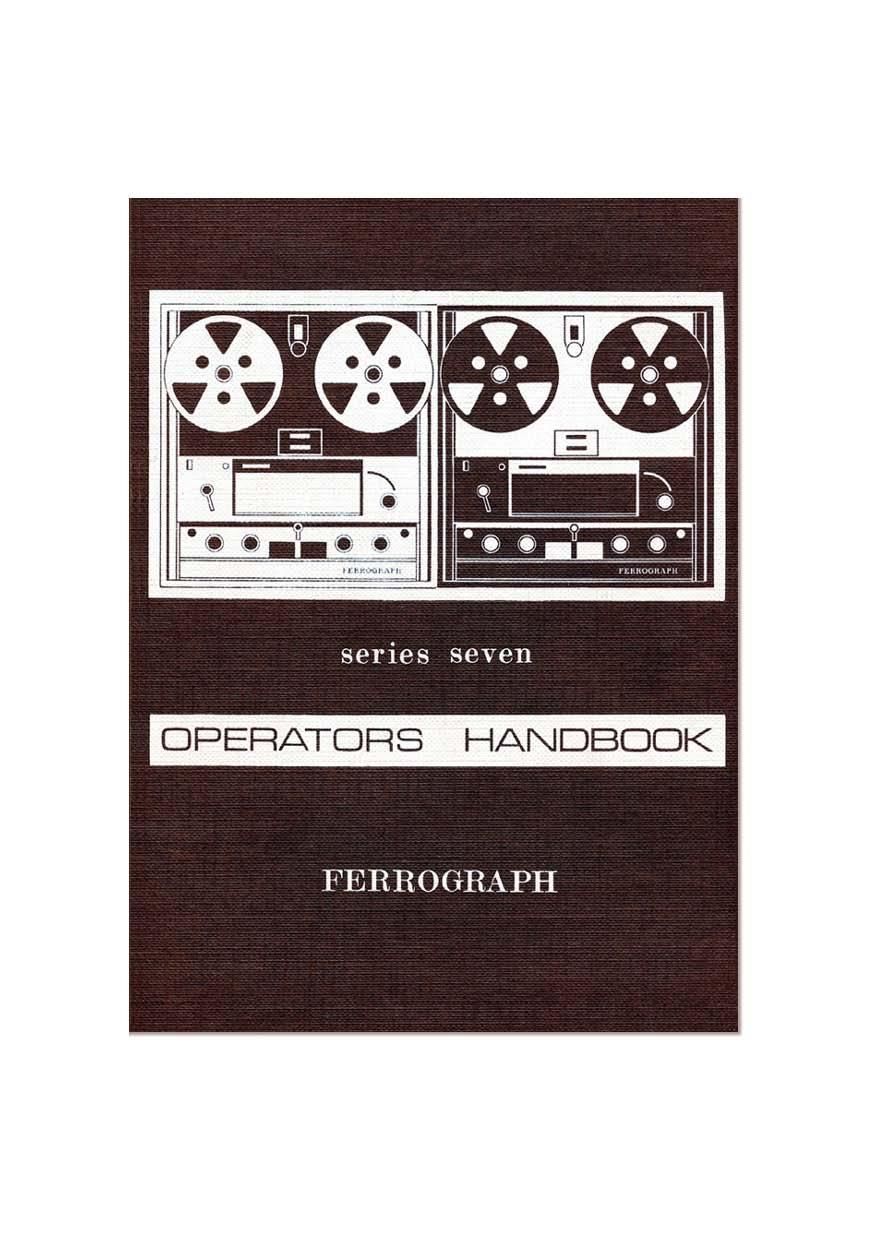
Ferrograph 722 Owners Manual

This is the 68 pages manual for Ferrograph 722 Owners Manual.
Read or download the pdf for free. If you want to contribute, please mail your pdfs to info@audioservicemanuals.com.

Page: 1 / 68
left right
Ferrograph 722 Owners Manual

Extracted text from Ferrograph 722 Owners Manual (Ocr-read)


Page 2

CONTENTS

Foreword ,.

General Specification
General Description
OPERATING INSTRUCTIONS

Connections

Power Supply . .

Inputs - Microphone
Tuner (radio)
Pick-up Cartridge
Other Sources t.

Outputs - Loudspeaker
Amplifier..
Tape Recorders
Headphones

Deck Operation .

Tape Loading

Tape Speed

Play

Record H

Automatic and Foil Stop
Fast Wind ,

Replay
Bass and Treble Controls

Output Switch . .
Meter Switch

Record .
Interjection
Stereo Models ..
Radio . . . .
Gramophone
Microphone .. .. ..
Characteristics . .
Placement .
Use of Microphone
Monitoring .. . .

Page 6

FEFIHCJGRAFH SEFIIES SEVEN

GENERAL SPECIFICATION

RECORDING MEDIUM
Magnetic tape. y wide. on reefs of up to 8%" diameter.
TRACK WIDTH
Full track ~ -248 in. (6-3 mm.); g track -- -090 in. (2-3 mm.):
% track - '043 in. (1-1 mm)
HEAD GAP WIDTH
Record head - 250g in. (6-39); Replay head - 80y. in. (2p).
OPERATING TAPE SPEEDS
Three (3): -7&, 3%, 1i in/sec. (19, 9-5, 4-75 cm/sect)
Suffix H 15, 7}. 3% in/sec. (38, 19. 9-5 cm/see)
TAPE SPEED ACCURACY
Better than 131% (at specified supply frequency).
PLAYING TIME PER TRACK
2,400 ft. (720 m) of tape-1 hr. 4 min. at 7; in/sec. (19 cm/sec.)
2 hr. 8 min. at 3% in/sec, (9-5 cm/sec.)
FAST WIND TIME

Continuously variable in either direction: at fast speed less than
1 min. for 1,200 ft. (360 m.) of tape.

"WOW" AND "FLUTTER"
Less than 008% at 7; ins/sec, (19 cm/sec)
015% at 33 ins/sec. (9-5 cm/sec)
020% at 1% ins/sec. (4-75 cm/sec.)
High Speed Models (Suffix H)
Less than 0-0896 at 15 ins/sec (38 cm/sec.)
010% at 7% ins/sec. (19 cm/sec.)
0-15% at 3% ins/sec. (9-5 cm/seo)
FREQUENCY RESPONSE
Record-Replay. using Long Play Ferrotape type B.
15 ln/sec. (38 cm/sec.) : 30.20.000Hz iZdB
7; in/sec. (19.,cm/sec.) : 30-17.000Hz :ZdB H
3% in/sec. (9-5 cm/sec.) : 40-14,000Hz iSdB
1} in/sec. (4-75 cm/sec.) : 50- 7.000Hz i3dB
REPLAY CHARACTERISTIC
15 in/sec. (38 cm/sec) : 35;; sec.
7.1, in/sec. (19 cm/sec.) : 50/3180p sec.
3} in/sec. (9-5 cm/sec) : 90/318051 sec.
1% in/sec. (4-75 cm/sec.) : 120/1590p sec.

8

Page 23

these may be recorded individually as on a normal mono recorder.
However. it is inadvisable to adjust the Record Mode selector when
actually on Record as this may cause polarisation of the heads, and the
mode should be selected before pressing the Record button. When
recording monophonically on a stereo instrument. the Transfer switch
can be used as described on page 40. but except when specifically
required, it must be left at the central "Off" position.

Radio

The radio should be connected as on page 14 and after the radio
or tuner unit has been properly tuned in and its tone controls set to their
normal or highest fidelity positions. the recording can commence. The
meter should not read above OdB even on the loudest signals. but once
the correct gain setting has been found. there should be no necessity to
re-adjust it during the recording as the station or studio engineer will
be monitoring the programme and correcting the signal level so as
not to overload the transmitter.

Gramophone

The connections are given on page 15, and the appropriate gain
control should be adiusted for the correct record level. As the dynamic
range on disc is very similar to that on tape, once the gain control has
been set so that the meter does not quite rise above OdB on the loudest
passages. it should not be necessary to re-adjust it during the transcrip-
tron.

Microphone

When using a microphone in the same room as the recorder. it is
essential that the internal (or external) loudspeaker be silent. or acoustic
feedback will occur. This takes the form of a "howl" as the noise from
the loudspeaker is picked up by the microphone, amplified and trans-
mitted again by the loudspeaker in a vicious circle, gradually building
up in volume. If it is required to listen to the signal. headphones must
be used or the signal can be monitored visually on the meter (see page
27).

The chief point of difference between live recording and recording
from the radio is that the studio control of dynamic range in the latter
is not present. This means that more attention must be paid to the
signal level meter and the gain control settings. Depending upon the
dynamic range of the programme material. a certain amount of volume
compression may be necessary. This involves reducing the level of
the loudest passages and increasing that of the weakest so that the
former does not overload the tape nor the latter become lost in the
background noise. However. too drastic use of the gain control should

25

Page 59

a small treble lift, followed by a sharp fall in the response, at the extreme
of the frequency range. This removes any FLF. bias pick-up and
ensures that the response extends only slightly beyond a chosen limit
for each tape speed. thus reducing hiss to a minimum. The muting of the
high frequencies during last wind is provided by switching in R313
and C312.

The output signal from the replay board passes to the "Tape level"
control marked "A" under the hinged flap on the control panel.

Meter and Tone Control Board

The input signal for this board comes treat the "Output" switch
$W702 (or SW703). and is either "Source" or "Tape as selected
manually by the Output switch. The signal is amplified by VT400.
which has a small voltage gain, and fed to the emitter follower VT40l
which gives an output of 2V at approximately 30 u. The impedance is
made up to 60012 to drive the Line output by the series resistor R406.
but it drives the VU meter directly. thus avoiding the slight distortion
of the signal which would occur due to the meter rectifier if this was
driven from the higher impedance 600 t) point. As is usual with VU
meters. an offset of 4dB is used between sine wave and music signals.
an indication of 0 VU on music signals corresponding to maximum
recording level (32me/mm.).

The signal then passes to the tone control stage VT402. which has no
mid-lrequency gain but provides boos! or cut at both ends of the audio
band With a clearly defined central level position for the Bass and
Treble controls, The signal is fed to the Low Level output and "Output"
control via R417 which on the stereo models enables both channelsto be
connected together without any increase in distortion, if required The
Output control varies the signal fed to the Power Amplifier Board,

The Output control is a linear potentiometer feeding into a relatively
low impedance in order to give an effective logarithmic characteristic.
This arrangement has been found to be more consistent than logarithmic
potentiometers and gives excellent balance on all gain settings on
stereo models

Power Amplifier Board

This is located on the power unit. attached to a heat sink, and it
consists of a transformerless arrangement with heavy negative feedback
taken from both sides of the loudspeaker coupling capacitor C500.
Resistor R511 provides feedback down to 0.0. ensuring high stability
even on reactive loads, while feedback via R512 reduces the effective
reactance of C500 to an insignificant value, Control of the quiescent
current in the output stage is effected by R506. which is adjusted for
approximately 25mA total current for the board. Correction of the
quiescent current for ambient temperature variations is obtained from
the forward resistances of MRSOO it 501.

62

Page 63

" POWER
AMPLIFIER AMPLIFIER
BOARD BOARD

HS 3! SVEREO POWER UNIV

Page 65

APPENDIX A

OPERATIONAL FAULT ANALYSIS

Symptoms

Possible Operational Causes

. No "On" lamp: tape
will not run.

Mains fuse blown. Mains lead or
plug not properly titted. Mains
selector knob loose or wrongly
positioned.

. "Reset" lamp illumin-
ated: tape will not
run.

Tape wrongly set round auto-
stop. or foil on tape contacting
foil stop. Speed selector and
Equalisation switches not set to
same speed.

. "Reset" lamp not on
but tape will not run.

Speed selector has been turned
when Function switch not at
"Stop". Return to "Stop" and
turn Speed Selector to adjacent
speed then back again.

.After turning from
"Run" to "Stop".
Function switch will
not return to "Run.

Function switch has been turned
too far and Fast wind catch has
engaged. To clear. move "Lock
Release" sideways.

, Known, well recorded
tape will not play;
tape runs but no indi-
cation on meter,

Output switch at "Source". Tape
incorrectly positioned in heads,
Piece of splicing tape sticking on
replay head. D.C. fuse blown.
Replay control "A" at minimum.

.Tape runs, indication
on meter but no sound
from speaker.

7. Tape replays but with
poor frequency res-
ponso.

"Output" control at zero. In»
correctly wired plug in Speaker
output. Short circuit plug in Low
Level output.

Bass and/or Treble controls in-
correctly set. Accumulation of
dirt or tape oxide over replay head
gap.

68

Page 67

Appendix A-Stereo Models only

Symptoms Possible Operational Causes

16. W h e n recording Transfer switch not set to "Off"
stereophonicallv.
breakthrough of one
track to the other.

17. When recording Record Mode switch set to wrong
monophonically, does position.
not erase or record.

APPENDIX B

The following accessories are available for use with the Ferrograph.

Carrying Case for Series Seven Ferrograph

Best quality waterproof canvas with zip fastener; gives full protection
against rain and dust.

Dust Cover

Attractive rigid transparent cover to protect the mechanism from
dust. etc.

Defluxer
For demagnetising record and replay heads. Prevents hiss and

protects tapes from cumulative background noise (see Note at front
of Manual).

70