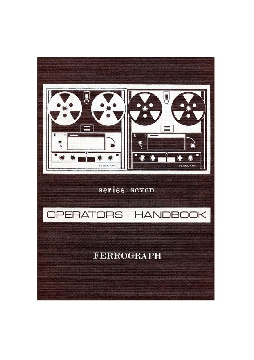
Ferrograph 713 Owners Manual

This is the 68 pages manual for Ferrograph 713 Owners Manual.
Read or download the pdf for free. If you want to contribute, please mail your pdfs to info@audioservicemanuals.com.

Page: 1 / 68
left right
Ferrograph 713 Owners Manual

Extracted text from Ferrograph 713 Owners Manual (Ocr-read)


Page 2

CONTENTS

Foreword ,.

General Specification
General Description
OPERATING INSTRUCTIONS

Connections

Power Supply . .

Inputs - Microphone
Tuner (radio)
Pick-up Cartridge
Other Sources t.

Outputs - Loudspeaker
Amplifier..
Tape Recorders
Headphones

Deck Operation .

Tape Loading

Tape Speed

Play

Record H

Automatic and Foil Stop
Fast Wind ,

Replay
Bass and Treble Controls

Output Switch . .
Meter Switch

Record .
Interjection
Stereo Models ..
Radio . . . .
Gramophone
Microphone .. .. ..
Characteristics . .
Placement .
Use of Microphone
Monitoring .. . .

Page 8

GENERAL DESCRIPTION

The Series Seven Ferrographs retain the basic 3 motor drive system of
the earlier models. but have completely redesigned mechanics with
solenoid operation. This enables the tape to be started and stopped by
remote switching. and on Record and Replay the recorder can be
controlled by a time switch.

The main functions of the deck (Fast, Stop, Pause, Run) are selected
by a single knob, with a separate press button for Record. On fast wind
the direction and speed oi wind are governed by a separate control.
An automatic stop operates at the end of the reel and the 4-digit turns
counter is gear driven from the takeAup spool.

Reel retainers are fitted to the reel carriers, which will accommodate
all types of spool conforming to the international standard. Three tape
speeds are available on each deck. and tension arms provide slur-free
starting at all tape speeds. The easy access head block gives straight
line tape loading. and the deck can be operated in either horizontal or
vertical positions.

Each deck is fitted with separate Erase. Record and Replay heads. so
that off-the-tape monitoring is possible whilst recording, and the Output
switch gives instant comparison of the original and recorded signals. This
can be done aurally on the two internal loudspeakers or the signal levels
can be checked visually on the meter. which can also be switched to read
the record bias.

Up to 10 Watts is available from the output stage and this can be
made subject to separate Bass and Treble control giving boost or cut.
Either internal or external loudspeakers may be used and an alternative
Low Level output is provided. There is also a 6009 emitter follower
output which will give a signal independent of the Output. Bass and
Treble controls. The tape can also be monitored on fast wind (but
muted to avoid discomfort) for accurate place location on the tape.

On record. mixing is given by separate gain controls for the Micro-
phone input and the Line input (suitable for radio or crystal and ceramic
pick-ups). All connections (except the Microphone input) are on a
panel at the rear of the recorder, and the instrument is mounted on a
rigid metal frame which facilitates removal from its portable case and
its inclusion in alternative cabinets.

10

Page 27

l MONO I I STEREO -l

r///- A l-"w-l-e m;__i
.m m...
I\\ ¢.\\l m [Tam

FIG. 10. TRACK DISPOSIYIONS-OUARTER TRACK

reversed at the end of the reel. However. when used monophonically on
"upper", the stereo recorders will operate exactly as described for the
mono recorder above.

The quarter track stereo arrangement is shown in Fig. 10. After
recording on tracks 1 Er 3 the tape can be reversed and another recording
made on tracks 2 it 4 as shown. When recording monophonically the
usual track sequence is 1 - 4 - 3 - 2. This is obtained by first recording on
"upper" on side A of the reel (track 1). At the end of the reel the tape
is reversed and recorded on side B. still on "upper" (track 4). Reversing
the tape at the end. recording takes place on "lower" on side A (track 3).
leaving the final recording on "lower" on side B (track 2).

Editing and Splicing

One of the advantages of a tape recording is that it is easrly edited:
unwanted passages may be cut out and the ends rejoined In this way a
composite programme of selected material may be built up. Of course. it
is only possrble to edit one mono track. as cutting out or splicing in
pieces of tape obviously affects both tracks. However. once the editing
has been done for the single track, the composrte tape may be put back
on the recorder and the other track recorded in the normal way with
material which does not require editing.

Splicing and jouning the ends of cut or broken tape is normally
carried out by means of suitable adhesive tape applied to the back of
the magnetic tape. which is usually the more polished Sides For joining
together two lengths of tape with as unobtrusive a joint as possible. a
diagonal cut at 45 to the edge of the tape is used. This produces a
"silent" ioint and minimises any "drop-out effect which may occur
if the two ends of the tape do not meet quite accurately. When editing
tapes, particularly when removing single words or noises. a vertical
joint at right angles to the tape edge is often used, and this is also
suitable for adding leader tapes and inserting stop foils. With either

29

Page 63

" POWER
AMPLIFIER AMPLIFIER
BOARD BOARD

HS 3! SVEREO POWER UNIV