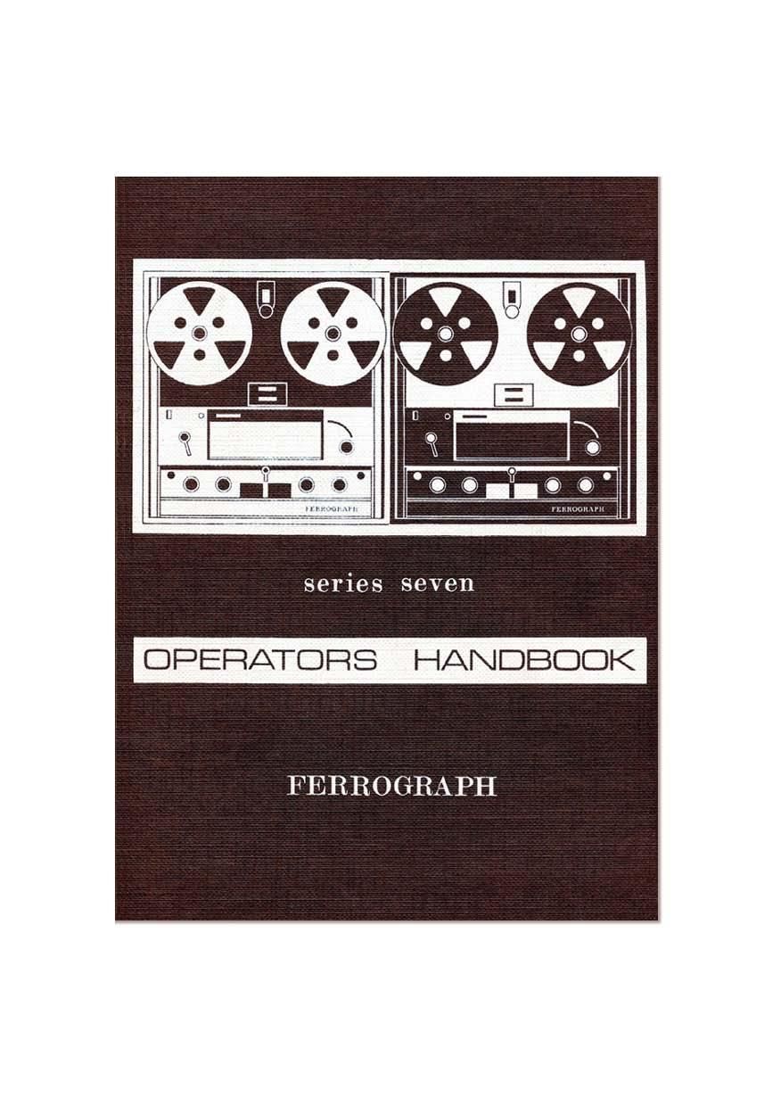
Ferrograph 702 Owners Manual

This is the 68 pages manual for Ferrograph 702 Owners Manual.
Read or download the pdf for free. If you want to contribute, please mail your pdfs to info@audioservicemanuals.com.

Page: 1 / 68
left right
Ferrograph 702 Owners Manual

Extracted text from Ferrograph 702 Owners Manual (Ocr-read)


Page 2

CONTENTS

Foreword ,.

General Specification
General Description
OPERATING INSTRUCTIONS

Connections

Power Supply . .

Inputs - Microphone
Tuner (radio)
Pick-up Cartridge
Other Sources t.

Outputs - Loudspeaker
Amplifier..
Tape Recorders
Headphones

Deck Operation .

Tape Loading

Tape Speed

Play

Record H

Automatic and Foil Stop
Fast Wind ,

Replay
Bass and Treble Controls

Output Switch . .
Meter Switch

Record .
Interjection
Stereo Models ..
Radio . . . .
Gramophone
Microphone .. .. ..
Characteristics . .
Placement .
Use of Microphone
Monitoring .. . .

Page 6

FEFIHCJGRAFH SEFIIES SEVEN

GENERAL SPECIFICATION

RECORDING MEDIUM
Magnetic tape. y wide. on reefs of up to 8%" diameter.
TRACK WIDTH
Full track ~ -248 in. (6-3 mm.); g track -- -090 in. (2-3 mm.):
% track - '043 in. (1-1 mm)
HEAD GAP WIDTH
Record head - 250g in. (6-39); Replay head - 80y. in. (2p).
OPERATING TAPE SPEEDS
Three (3): -7&, 3%, 1i in/sec. (19, 9-5, 4-75 cm/sect)
Suffix H 15, 7}. 3% in/sec. (38, 19. 9-5 cm/see)
TAPE SPEED ACCURACY
Better than 131% (at specified supply frequency).
PLAYING TIME PER TRACK
2,400 ft. (720 m) of tape-1 hr. 4 min. at 7; in/sec. (19 cm/sec.)
2 hr. 8 min. at 3% in/sec, (9-5 cm/sec.)
FAST WIND TIME

Continuously variable in either direction: at fast speed less than
1 min. for 1,200 ft. (360 m.) of tape.

"WOW" AND "FLUTTER"
Less than 008% at 7; ins/sec, (19 cm/sec)
015% at 33 ins/sec. (9-5 cm/sec)
020% at 1% ins/sec. (4-75 cm/sec.)
High Speed Models (Suffix H)
Less than 0-0896 at 15 ins/sec (38 cm/sec.)
010% at 7% ins/sec. (19 cm/sec.)
0-15% at 3% ins/sec. (9-5 cm/seo)
FREQUENCY RESPONSE
Record-Replay. using Long Play Ferrotape type B.
15 ln/sec. (38 cm/sec.) : 30.20.000Hz iZdB
7; in/sec. (19.,cm/sec.) : 30-17.000Hz :ZdB H
3% in/sec. (9-5 cm/sec.) : 40-14,000Hz iSdB
1} in/sec. (4-75 cm/sec.) : 50- 7.000Hz i3dB
REPLAY CHARACTERISTIC
15 in/sec. (38 cm/sec) : 35;; sec.
7.1, in/sec. (19 cm/sec.) : 50/3180p sec.
3} in/sec. (9-5 cm/sec) : 90/318051 sec.
1% in/sec. (4-75 cm/sec.) : 120/1590p sec.

8

Page 8

GENERAL DESCRIPTION

The Series Seven Ferrographs retain the basic 3 motor drive system of
the earlier models. but have completely redesigned mechanics with
solenoid operation. This enables the tape to be started and stopped by
remote switching. and on Record and Replay the recorder can be
controlled by a time switch.

The main functions of the deck (Fast, Stop, Pause, Run) are selected
by a single knob, with a separate press button for Record. On fast wind
the direction and speed oi wind are governed by a separate control.
An automatic stop operates at the end of the reel and the 4-digit turns
counter is gear driven from the takeAup spool.

Reel retainers are fitted to the reel carriers, which will accommodate
all types of spool conforming to the international standard. Three tape
speeds are available on each deck. and tension arms provide slur-free
starting at all tape speeds. The easy access head block gives straight
line tape loading. and the deck can be operated in either horizontal or
vertical positions.

Each deck is fitted with separate Erase. Record and Replay heads. so
that off-the-tape monitoring is possible whilst recording, and the Output
switch gives instant comparison of the original and recorded signals. This
can be done aurally on the two internal loudspeakers or the signal levels
can be checked visually on the meter. which can also be switched to read
the record bias.

Up to 10 Watts is available from the output stage and this can be
made subject to separate Bass and Treble control giving boost or cut.
Either internal or external loudspeakers may be used and an alternative
Low Level output is provided. There is also a 6009 emitter follower
output which will give a signal independent of the Output. Bass and
Treble controls. The tape can also be monitored on fast wind (but
muted to avoid discomfort) for accurate place location on the tape.

On record. mixing is given by separate gain controls for the Micro-
phone input and the Line input (suitable for radio or crystal and ceramic
pick-ups). All connections (except the Microphone input) are on a
panel at the rear of the recorder, and the instrument is mounted on a
rigid metal frame which facilitates removal from its portable case and
its inclusion in alternative cabinets.

10

Page 12

Power Supply

The mains voltage selectors are on either side of the mains plug at
the centre of the rear panel. If not already set to the local supply voltage
they should be pulled outwards to disengage (they will not come
entirely free), rotated until the correct voltage range is opposite the
indicator. then pushed home firmly. Always set both Selector Knobs
to the same voltage range. The mains lead and socket can now be
plugged into the recorder with the appropriate plug fitted to the other
end to connect to the power supply (red or brown - Live, blue - Neutral.
green or green/yellow - Earth). The instrument is energised by the
switch at the rear centre of the deck. when the "On" lamp will be
illuminated.

I n puts
Microphone

Medium impedance microphones (250-10000) can be plugged
directly into the Microphone input (300pV-15mV) on the front panel
and reasonably long leads used (the maximum length will depend
upon local conditions e.g. sources of hum, interference. etc). When
using a low impedance (30-509) microphone, a matching unit is
necgssary (e.g. TA/SO/ML in appendix B) and very long leads can be
use .

smut

:2? 3E3":ID

unm

FIG. 2. JACK PLUG WIRING

Tuner (radio)

The output from most tuner units may be fed directly into the "Line"
input, which will accept signals from 50mV to 10V (input impedance
2M0). and this will also apply to the "Tape"; "Tape Output and
"Tape Recorder" sockets on modern radios. Unless stated otherwise
in the tuner instructions, screened lead should be used for this connec-
tion. In the unlikely event of the signal being too weak for the "Line"
input. it may be plugged into the Microphone input.

When recording from V.H.F. (FM) stereo receivers. no extra filters
are necessary.

14

Page 19

u

53
u

TIME ELAPSED (nu
FIG. 0. TURNS COUNTER GRAPH

I
ll

t
2|

2"
ID

Iu/sEc
mate I

a
. : -

COUNTER READING (turns)

:t

Nata-When the "Fast Wind" knob is adjusted so that the tape is
stationary. the power is being dissipated entirely as heat, and it is
therefore inadvisable to leave the Function knob at "Fast" for a long
period. As soon as the tape comes to rest, the Function knob should
be returned to "Stop.

21

Page 31

Approximate Length of Tape Per Reel
Size of Standard Long or Double Triple
Reel Play Extra Play Play Play

3 in. 150 ft. 225 ft 300 ft. 450 ft.

3} in. . 7720070. 300 ft. 400 ft. 600 ft.

4 in. 300 ft. 450 ft. 600 ft 900 ft.

43; in, 400 ft. 600 ft. 900 ft 1,200 ft.

5 in. 600 ft. 900 ft. 1,200 ft. 1,800 ft

5% in. 900 ft 1,200 ft. 1,800 ft. 2400 ft.-

7 in. 1.200 ft, 1800 ft. 2,400 ft. 3.600 ft;
- 8% in. 1,800 ft, 2,400 ft. 3,600 ft, 4800 fir-1
Tape

The Series Seven Ferrograph is set up for use with Ferrotapei and its
specification is obtained using tape of similar quality and characteristics.
As supplied the bias is set for "low noise" tape such as Ferrotape
type B, Scotch Dynarange tape. etc and certain continental tapes, but
if it is required to use Ferrotape type A and other similar tapes, the bias
can be adjusted for optimum results as outlined in the Technical
Section, page 46.

In addition to Standard and Long Play Tapes, Double Play tape can
be used with satisfactory results. particularly at the slower speeds
where its more flexible backing gives a more intimate contact with the
working face of the head, leading to a more constant output, especially
at the higher frequencies. Triple and Quadruple Play tapes can also be
used, but due to their different oxide formulation they give greater
distortion at the higher recording levels and the recording should be
made at a lower level than usual They may also give excessive output at
the higher frequencies

33

Page 35

FIG. I1 HEAD BLOCK-STEREO

When recording monophonically on the stereo models, the Transfer
swrtch can be used to apply echo Without external connections. as
described on page 43.

Use as an Amplifier

By setting the "Output" switch to "Source". the Series Seven
Ferrograph can be used as a "straight-through amplifier. providing up
to 10 Watts output to the internal or external loudspeaker(s). It can be
used in conjunction with a tuner unit. radio or turntable. or it can be
used with a microphone as a public address" system. The mixing
facilities can be used and the output signal modified by the Bass and
Treble controls.

Cabinet Mounting

The Series Seven Ferrograph can be fitted into consoles or cabinets
With or Without its standard case. When in the case it will fit into a space
16% in wide by 17,} in. long and about 7; in, deep with 2% in. top
clearance, The 7 in reels will fit within the confines of the deck, but
8% in. reels will overlap the case by about i in at each stde.

To remove the recorder from its case. it should be stood vertically
(handle at the top. amplifier at the bottom) and all connections to the
rear panel removed, also all fuses. The handle should be lifted and first
one end then the whole handle pushed down into the recess to take it
clear of the inside ofthe case (Fig. 15), when the four bolts on the floor
of the case can be unscrewed. The recorder chassis should be slid
forward and the two loudspeaker leads unplugged. one at each side,
when the chassis can be lifted clear of the case.

37

Page 43

TECHNICAL DETAILS

This section contains technical information and descriptions of
circuitry to enable the more sophisticated user to obtain maximum
benefit from the instrument. However. while explanations are given
in detail. re-adjustment of pre-set controls should be attempted only
if possessed of adequate knowledge.

Record

The basic connections and recording functions are described on
pages 14 8 24 but the following notes are apposite.

Crystal Pick-up

While overloading will not occur when feeding high output crystal
pick-ups into the Line input. it may be that the gain control is operating
over an inconveniently small part of its range. This can be cured by
connecting a capacitor (1.800 pf) across the leads viz, in parallel
with the pick-up, when the output will be attenuated to a more
suitable level.

Constant Tones (Frequency Response)

When recording constant tones (eg. sine wave) from a source
connected as in page 14. a level of recording higher than that suitable
for audio signals is sometimes permissible, The signal level meter
has the standard VU characteristic which calibrates 0 VU on the scale
as 4dB below peak recording level to allow for transient peaks in the
average audio signal leg. orchestral music). and thus constant tones
of up to 2000Hz approximately can be recorded at +3dB on the meter
scale without overloading the tape. With frequencies above this it is
necessary to record at a lower level to avoid tape saturation due to the
ore-emphasis of the record characteristic. Accordingly. recordings
of a wide range of tones such as a frequency response check should
be made with a reference level of 20dB below peak recording level.

Bias A d/ustment

The bias on the Series Seven Ferrograph can be adjusted by the screw-
driver pre-set control 'B' at the front of the recorder and its value can
be observed on the meter by setting the Meter switch to read "Bias". The
meter is calibrated at 7% in/sec. such that at OdB the bias is suitable for
"Low Noise" tape such as Ferrotape type B or Scotch Dynarange tape,
and at -2dB it is suitable for the standard Ferrotape type A. The
recommended bias settings (equalisation switch at the 7:1; in/sec.
position) for various brands of tape are given below. These are intended
as a guide and tapes not included in the list can also be used on the
Ferrograph with average bias settings or with a suitable setting deter-
mined by experiment to give the best result.

46

Page 45

uss uuu

OUTPUT (ll)

IREQUNCV (N1)

FIG 18. EFFECT OF BASS AND TREBLE CONTROLS

Monitoring (Signal Level)

As the Series Seven Ferrograph has separate record and replay heads,
it is possible to monitor the signal off the tape whilst recording. and this
can be done aurally from the loudspeaker by setting the Output switch
too"Tape. and visually on the meter by setting the Meter switch to
" utput".

The record and replay signals are set so that the meter indication
on "Tape" is the same as on "Source" for easier comparison of the
signal quality. However, different brands of tape vary slightly in the
strength of the replay signal obtained and if the brand in use is markedly
different from that to which the recorder has been set. there will be an
observable difference between the readings. If it is desired to correct
for this, the two signals should be compared and the "Tape Level"
pie-set control "A" (see Fig 7 or 8) adjusted with a screwdriver
until the Tape" and "Source" indications on the meter are the same
(if recording constant tones see page 46)

48