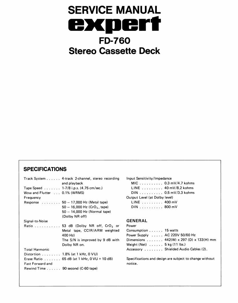
Expert fd 760 stereo cassette deck

This is the 15 pages manual for expert fd 760 stereo cassette deck.
Read or download the pdf for free. If you want to contribute, please mail your pdfs to info@audioservicemanuals.com.

Page: 1 / 15
left right
expert fd 760 stereo cassette deck

Extracted text from expert fd 760 stereo cassette deck (Ocr-read)


Page 1

FRONT VIEW REAR VIEW V U meter KL-258T-6 Cassette Holder N 2031 5 Knob 44 N41660 Cassette Key Cap (x S ) Knob 21 N41 53&SS N41661 Push Button (x 6) N42052-SS Cassette Key Cap N4153&SSR rr-r ra,rrrta /ar Lart oarDat Foot Bottorn No.7102 N20574 -2-

Page 2

PLAY AMP ALIGNMENT PROCEDURE Set the position of Rec. Volume to Max., 1) Head Azimuth RIP HEAD PLAY I (For Alignment points see page 5.) and of Bal. Volume, Bias Adj. to Center in allalignment. OUTPUT DOLBY AMP AMP LIN E OUT U \- 2l vu Meter LrN E rN DO LBY AMP OUTPUTMETER AMP +2dB (DOLBY LEVEL) CONF IRMED OUTPUT VO LTAG E 100mV QVM VU METER 400H2 PLAY AMP TP705, 706 DO LBY AMP TP705 ,706 ADJ V.M = 100mV OUTPUTMETER AMP \- \- RIP H EAD 3) PIay Back Level +2dB ADJ. Controls to be positioned Test Tape P roced u re Dolby NR : OFF MPX : OFF Tape Selecto r . NO R MA L Function : PLAY MTT.114 1 ) Adjust the head mounting screw in order to obtain max. V.M. indication. VU METER Contro ls to be positioned Test Tape P roced u re Dolby NR : OFF MPX : OFF Tape Selecto r . NO R MA L Function : REC. BIank Normal 1) Apply 400H2, approx. 40mV signal at the LINE lN terminal. 2) Make the voltage at TP705 and TP7 06 be 100mV by adjusting applied signal level. (GND: TP710) 3) Set the VU meter indication to DO LBY LEVE L (+2dB) (double D mark position) by the adjustment of SV RB 1 1 an d 812. Controls to be positioned Test Tape P roced u re Dolby NR : OFF MPX : OFF Tape Selector : NO R MA L Function : PLAY MTT.150 Ad just SV R 70 1 an d 702 to make the output voltage at Dolby testpoints of TP705 and 706 be 100mV. (G N D: TP7 10) -3-