Electro voice eliminator brochure

This is the 4 pages manual for electro voice eliminator brochure.
Read or download the pdf for free. If you want to contribute, please mail your pdfs to info@audioservicemanuals.com.

Page: 1 / 4
left right
electro voice eliminator brochure

Extracted text from electro voice eliminator brochure (Ocr-read)


Page 1

Electrol/oice -

Eliminator®
Amplifier

Stereo Power Amplifier
380 watts per channel at 8 ohms; 600
watts per dtannel at 4 ohms; am 850
watts per clanneI at 2 olms at 1 kHz

- 1,200 watts bridged at it aims;

1,700 watts bridged into 4 ohms
at1 ItHl

- Stated-dean limiters driven by a
sophisticated inputloutptl comparator
ensure lreedom from amplifier clipping

- High-current Neutrilt Spealton' outpta
comectors tor channels A, B and bridged
operation tor loss-free oomections

- Active-balanced XLR-Iype inn! and
paralleled XLR-type output connectors
provide easy signal routing

- Rear-rimmed dB-scaled detented level
oomrols tor easy corlrol of gain

Description

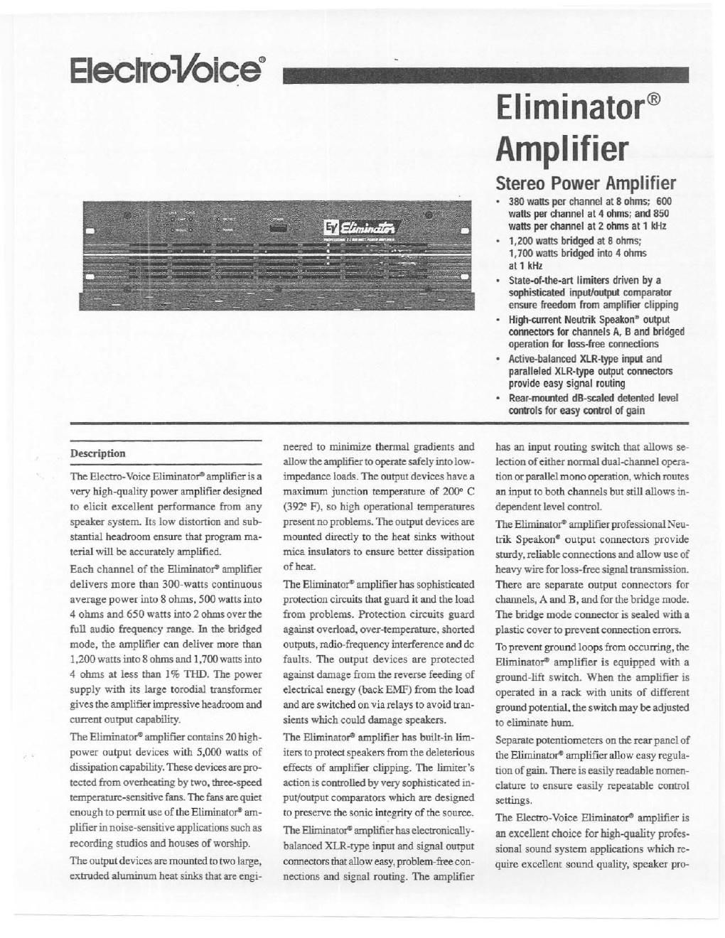
The Electra-Voice Eliminator' amplifier is a
very high-quality power amplifier designed
to elicit excellent performance from any
speaker system Its low distortion and sub-
stantial headroom ensure tltat program ma-
terial will be accurately amplified.

Each channel of the Eliminator" amplifier
delivers more than 300-watts continuous
average power into 8 ohms, 500 watts into
4 ohms and 650 watts into 2 ohms overthe
full audio frequency range. In the bridged
mode. the amplifier can deliver more than
1,200 watts into 8 ohms and 1,700 warts into
4 ohms at less than 1% 'IHD. The power
supply with its large torodial transformer
gives the amplifier impressive headroom and
current output capability

The Eliminator amplifier contains 20 high-
power output devices with 5,000 watts of
dissipation capability. These devices are pro-
tected from overheating by two. three-speed
temperature-sensitive fans. The fans are quiet
enough to permit use of the Eliminator' am-
plifier in noise-sensitive applications such as
recording studios and houses of worship.
The output devices are mounted to two large,
extruded aluminum heat sinks that are engi-

neered to minimize themal gradients and
allow the amplifier to operate safely into low
impedance loads. The output devices have a
maximum junction temperature of 200° C
(392° F). so high operational temperatures
present no problems The output devices are
mounted directly to the heat sinks without
mica insulators to ensure better dissipation
of heat

The Eliminator amplifier has sophisticated
protection circuits that guard it and the load
from problems. Protection circuits guard
against overload. oveHemperature. shorted
outputs. radio-frequency interference and dc
faults. The output devices are protected
against damage from the reverse feeding of
electrical energy (back EMF) from the load
and are switched on via relays to avoid tran-
sients which could damage speakers.

The Eliminator amplifier has built-in lim-
iters to protect speakers from the deleterious
effects of amplifier clipping. The limiters
action is controlled by very sophisticated in-
put/output comparators which are designed
to preserve the sonic integrity of the source.
The Eliminator amplifier has electronically-
balanwd XLR-rype input and signal output
connectors that allow easy, problem~fiee con-
necuons and signal routing. The amplifier

has an input routing switch that allows se-
lection of either normal dual-channel opera-
tion or parallel mono operation. which routes
an input to both channels but still allows in-
dependent level conuoL

The EliminatorD amplifier professional Neu-
trik Speakon output connectors provide
sturdy, reliable connections and allow use of
heavy wire for loss-free signal transmission.
There are separate output connectors for
channels, A and B, and for the bridge mode.
The bridge mode connector is sealed with a
plastic cover to prevent connection errors.
To prevent ground loops from occurting, the
Eliminator amplifier is equipped with a
ground-lift switch. When the amplifier is
operated in a rack with units of different
ground potential. the switch may be adjusted
to eliminate hum

Separate potentiometers on the rear panel of
the Eliminatot amplifier allow easy regula-
tion of gain. There is easily readable nomen-
clature to ensure easily repeatable control
settings.

The Electro-Voice Eliminator amplifier is
an excellent choice for high-quality profes-
sional sound system applications which re-
quire excellent sound quality. speaker pro-

Page 2

Eliminator Stereo Power Amplifier

Eliminator Stereo Power Amplifier

tection and the highest level of commotion
quality and longvtenn reliability.

Architects and Engineers
Specifications

The power amplifier shall be a dual-channel
model of solid-state design employing high-
powcr output devices in a true-complemen-
tary-symmetry output circuit. It shall be ca-
pable of operating from a 120/220/240-V. 50/
60 Hz ac line. The power amplifier shall meet
various worldwide safety standards includ-
ing Underwriter's Laboratories [TL-813 stan-
dard. Canadian Standards and CE standards.
The power amplifier shall contain a limiter
circuit driven by a high-quality input/output
comparator to protect the load from damage
by amplifier clipping. The amplifier shall
contain sensing circuitry to provide protec~
tion for the output transistors against
overtemperature. excessive output voltage.
shoned loads. excessive phase shift and
back»EMF current. The load shall be simi-
larly protected against stan-up/shutdown
transients. low ac line voltage and dc.
Rear-mounted controls shall include detented
level potentiometers for each channel, an
input routing switch for selecting dual/ste-
reo or parallel mono operation. a switch for
selecting dual/stereo or bridged operation
and a chassis groundlift switch. Rear-
mounted input connectors shall include a 3-
pin female XLR-type connector wired in
parallel with a male 3 connector for signal routing. Output connec~
tors shall be Neutrik Speakon NlAMPs for
channels A and B. and another for bridged
operation.

Front-panel indicators shall include power
on. a protection indicator and separate sig-
nal present and limiter indicators for each
channel. Front-panel controls shall include
a power on switch.

The power amplifier shall meet the follow-

ing performance specifications: rated output
power from 2020.000 Hz at less than 0.2%
THD. each channel 300 watts into 8 ohms.
500 watts into 4 ohms and 650 watts into
2 ohms. In bridged mode at 1 kHz. the
amplifier shall deliver 1.200 watts into
8 ohms and 1,700 watts into 4 ohms. Hum
and noise shall be at least 103 dB
(A weighted) below rated output power;
damping factor shall be greater than 300
at any frequency up to 1 kHz in any mode
with an 8-ohm load; THD (total harmonic
distortion) shall be less than 0.05% at 1 kHz
at rated output power; crosstalk shall be bet-
ter than -80 dB at 1 kHz at rated output
power. transient intermodulation distortion
(DIM 30). shall be less than 0.03%. Dimen-
sions shall be 132.5 mm (5.25 in) high x 483
mm (19.0 in) width x 385.5 mm (15.7 in)
deep. Net weight shall be 16 kg (35.2 lb).
Color shall be light gray. '
The power amplifier shall be the Electro-
Voice Elirninator' amplifier.

Limited Warranty

Electro-Voice products are guaranteed
against malfunction due to defects in mate-
rials or workmanship for a specified period,
as noted in the individual product-line
statement(s) below. or in the individual prod-
uct data sheet or owner s manual. beginning
with the date of original purchase. If such
malfunction occurs during the specified pe-
riod. the productwillberepaired orreplaced
(at our option) without charge. The product
will be returned to the customer prepaid Ex-
clusions and Limitations: The Limited
Warranty does not apply to: (a) exterior fin»
ish or appearance; (b) certain specific items
described in the individual product-line
statement(s) below. or in the individual prod-
uct data sheet or owners manual; (c) mal-
function resulting from use or operation of
the product other man as specified in the

product data sheet or owner's manual; (d)
malfunction resulting from misuse or abuse
of the product; or (e) malfunction occurring
atanytimeafterrepairshave beenmadeto
the product by anyone other than Elecoo-Voice
Service or any of its authorized service repre-
sentatives. Obtaining Warranty Service:
To obtain warranty service, a customer must
deliver the product. prepaid, to Elector-Voice
Service or any of its authorized service rep-
resentatives together with proof of purchase
of the product in the form of a bill of sale or
receipted invoice. A list of authorized ser-
vice representatives is available from Eleono-
Voice Service at 600 Cecil Street. Buchanan,
Ml 49107 (800/234-6831 or FAX
616/695-4743). Incidental and Conse-
quential Damages Excluded: Product re-
pairorteplacement and returntothecustorner
are the only remedies provided to the cus-
tomer. Electra-Voice shall not be liable for
any incidental or consequential damages in-
cluding, without limitation. injury to persons
or property or loss of use. Some states do not
allow the exclusion or limitation of inciden-
tal or consequential damages so the above i
limitation orexclusion may not apply to you.
Other Rights: This warranty gives you spe-
cific legal rights, and you may also have other
rights which vary from state to state.
Electra-Voice Electronics are guaranteed
against malfunction due to defects in mate-
rials or workmanship for a period of three
(3) years from the date oforiginal purchase.
Additional details are included in the Uni-
form Limited Warranty statement

For warranty repair or service infer-nia-
tion. contact the service repair department
at: 616/695-6831 or 800/685-2606.

For technical assistance, contact Technical
Support at 80012346831 or 616/695-6831.
M-F. 8:00 am. to 5:00 pm Eastern Stan~
dard 'l'rme.

Specifications subject to change without
notice.