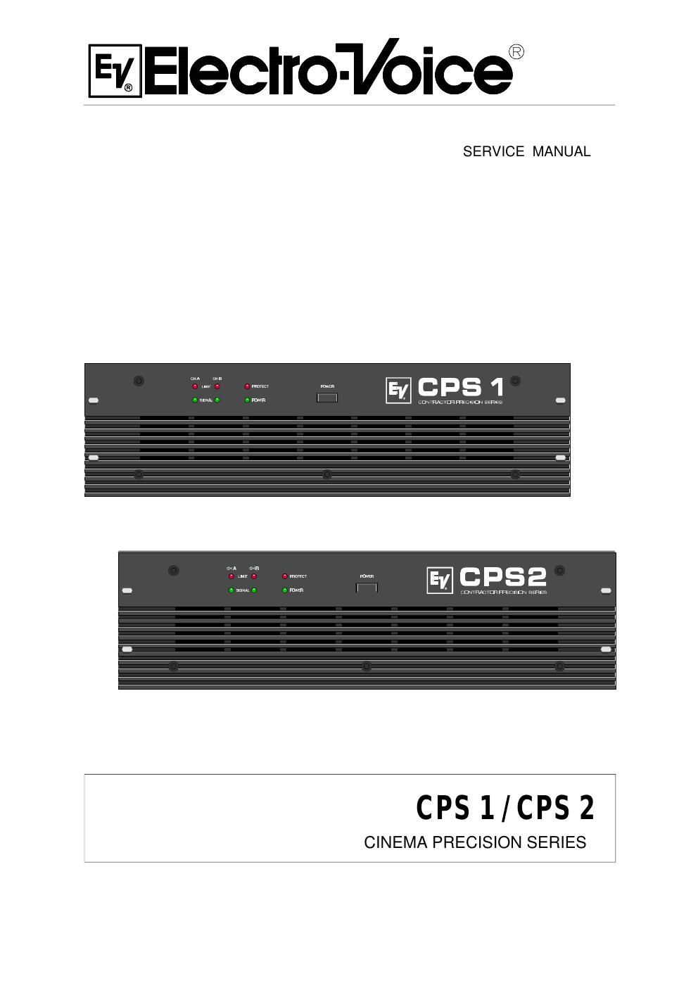
Electro voice cps 1 2 service manual

This is the 18 pages manual for electro voice cps 1 2 service manual.
Read or download the pdf for free. If you want to contribute, please mail your pdfs to info@audioservicemanuals.com.

Page: 1 / 18
left right
electro voice cps 1 2 service manual

Extracted text from electro voice cps 1 2 service manual (Ocr-read)


Page 1

Technical Specifications: CPS1, CPS2 Amplifier at rated conditions, both channels driven with 8 ohms loads, unless otherwise specified. CPS1 CPS2 Load Impedance 8 W 4 W2 W8 W4 W 2 W Maximum Midband Output Power 280W450W 650W 380W600W850W THD=1%, 1kHz Rated Output Power 230W350W450W 300W500W650W THD < 0, 2%, 20Hz ... 20kHz Maximum Bridged Output Power900W1300W -1200W1700W- THD=1%, 1kHz Maximum RMS Voltage Swing 56V 64V THD=1%, 1kHz Voltage Gain34dB 35dB at 1 kHz Slew Rate 25V/µs 30V/µs Power Consumption690W 870W at 1/8 maximum output power @ 4 W Input Sensitivity 0dBu ( 775mV) at rated output power @ 4 W, 1 kHz THD at rated output power, < 0.05 % MBW=80kHz, 1 kHz IMD-SMPTE < 0.08 % 60 Hz, 7 kHz DIM30< 0.03 % 3.15kHz, 15 kHz Crosstalk <-80 dB ref. 1kHz, at rated output power Frequency Response -1dB, ref. 1 kHz 13Hz ... 45kHz Power Bandwith THD=1%, ref. 1kHz, half power @ 4 W 10Hz ... 50kHz Input Impedance 20Hz ... 20 kHz, balanced 20kW Damping Factor at 100Hz / 1kHz >300 / >200 Signal to Noise Ratio A-weighted 103dB Power Requirements120V, 50Hz ... 60Hz ProtectionAudio limiters, High temperature, DC, HF, Back-EMF, Peak current limiters, Inrush current limiters, Turn-on delay Cooling Front-to-Rear, 3-stage-fans Safety Class I Dimensions (W x H x D), mm483 x 132.5 x 385.5 Weight15kg 16kgSPECIFICATIONS 7

Page 2

1 MEASUREMENT SPECIFICATIONS: CPS1 & CPS2 complete appliance printed board assembly names and their corresponding EDP-numbers:Printed board assembly EDP-number120V230VCPS1CPS2CPS1CPS284183841848418184182Printed board assemblyIndexMain PCB1Supply PCB4Input PCB2LED PCB3measuring condition; if not otherwise specified: -tolerance of measured values:DX = ±1.5 dB -measuring frequency:f = 1 kHz -stated levels refer to:U = 775 mV (0 dBu) -level controls set to their clockwise limits -pin assignment of the XLR-type connectors:PIN 1: ground / shielding PIN 2: + INPUT PIN 3: - INPUT -source resistance for the induction via the XLR-type connector:R(Q) = 50 W - the AMPLIFIER PCB printed board assembly is provided with service connectorsCNS1CNS2CNRCPINassignmentPINassignmentPINassignment1-Vcc1LIM A Switch1LIM Out A2BIAS +A2-15V2LIM Out B3BIAS -A3LIM B Switch3Standby via RC4FAN Voltage4+15V4Standby LED5+Vcc5AGND5-Vss6BIAS +B6Speaker Out A6+Vss7BIAS -B7Relais/Protect7n.c.8Temp Heatsink8Speaker Out B8n.c.1. Operating voltage: U(B) = 120V, 230V, 240V 50Hz ... 60Hz 2. Deviation limit of the operation voltage:-30% .... +10% 3. Power consumption (both channels driven) f = 1kHzCPS1CPS2Idling power consumption30-60W40-80WNominal power consumption (RL=4W)1400W1900WStandard power consumption (RL=4W)430W600WMaximum power consumption (RL=4W)1650W2100WPower consumption at 1/8 of the maximum output power690W870W