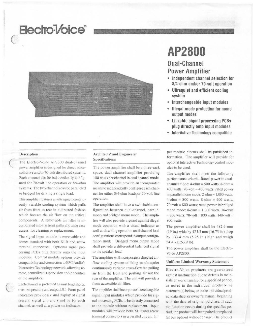
Electro voice ap 2800 brochure

This is the 4 pages manual for electro voice ap 2800 brochure.
Read or download the pdf for free. If you want to contribute, please mail your pdfs to info@audioservicemanuals.com.

Page: 1 / 4
left right
electro voice ap 2800 brochure

Extracted text from electro voice ap 2800 brochure (Ocr-read)


Page 1

Eleclrol/olce -

AP2800

Dual-Channel

Power Amplifier

- Independent channel selection tor
BIA-ohm and/or 70-volt operation

- Ultraqulet and efficient cooling
system

- Interchangeable input modules

0 Illegal mode protection for mono
output modes

- Linkahle signal processing PCBs
plug directly onto input modules

- lnterActive Technology compatible

Description

The Electro-Voice APZROU dual-channel
power amplifier is designed for direct mice-
cotl drive andmr 704 ll disin buted s) stems
Each channel can be independently config-
ured for 70-iolt lint: operation or tin-ohm
systems. The two channels can he paralleled
or bridged for driving a single load.

This amplifier leatures an ultraquiet. continu-
ously variable cooling system which pulls
air from front to tear in a directed fashion
which focuses the air flow on the critical
components. A remoi able air filter is in-
corporated into the tront grille allowing easy
access for cleaning or replacement,

The signal input module is removable and
comes standard with both XLR and screw
terminal connectors. Optional Signal pro-
cessing PCBs plug directl} onto the Input
modules Control module options proude
compatibility and connection to EVl Audio's
lnterncttveTechnology network. allowing re-
mote. centralivcd superiiston and/or control
of the amplifier.

Each channel is protected ngdinsl load Shmls.
over temperature and output DC. ant»panel
indicators provide a itsqu display ot signal
present. signal clip and stand by for each
channel. a.» well as a power on Indicator

Architects' and Engineers'
Specifications

The power amplifier shall be a three-rack

space. dual-channel amplifier providing
l0tl watts per channel in dual channel mode.
The amplifier will provide an incorporated
means to independently configure each chan-
nel for either Sl-l-ohm loads or 70~volt line
operation.

The amplifier shall have a switchable con-
figuration between dual-chartnel, parallel
mono and bridged mono mode. The ampli-
fier will also provide a guard against illegal
mode operation with a Visual indicator as
well as disabling operation until channel load
configurations correspond to output configu-
ration mode. Bridged mono output mode
shall prmide a differential balanced signal
to the speaker load.

The amplifier will incorporate a directed air-
flow cooling system utilizing an ultmquiel
continuously variable cross-flow fan pulling
air from the front and pushing air out the
rear ol'tlie amplifier. The unit will provide a
trnnt»accessible air filter.

The amplifier shall incorporate interchangahle
signal input modules which provide for Slg<
rial processing PCBs to be directly connected
lit the module without replacement. input
modules wull provide both XLR and screw
terminal connectors in a parallel Circuit. In-

put module pinouts shall he published in-
formation. The amplifier will provide for
optional Interactive Technology control mod-
ules to be used.

The amplifier shall meet the following
performance criteria. Rated power in dual-
channel mode: 4-ohm = 500 watts. 8-ohm =
400 watts. 70-volt = 400 watts; rated power
in parallel mono mode: l-ohm = LOOO watts.
4-ahm : 800 watts. 8«ohm = 400 watts.
70-volt = 800 watts: rated power in bridged
mono mode: S-ohm = l,000 watts. lfi-ohm
= 800 watts. 70-volt = 800 watts. Hamill =
800 watts.

The power amplifier shall he 482.6 mm
(19 in.) wide by 425.5 mm ( l6.75 in.) deep
by l33.4 mm (5.25 in.) high and weigh
24.4 kg (53.9 lb).

The power amplifier shall be the Elcclm-
Voicc AP2800.

Uniform Limited Warranty Statement

Electra-Voice products are guaranteed
against malfunction due to defects iii mate-
rials or workmanship for a specified period.
as noted in the individual product-line
statenicntis) below. or in the individual prod-
uct data sheet or owner's manual. beginning
With the date of original purchase. If such
malfunction occurs during the specified pe-
nud. the product will be repaired or replaced
(at our option) without charge. The product

Page 2

APZSOO Dual-Channel Power Amplifier

will be returned to the customer prepaid.
Exclusions and Limitations: The Limited
Warranty does not apply to: (a) exterior fin»
ish or appearance; (b) certain specific items
described in the individual product-line
statoment(s) below. or in the individual prod-
uct data sheet or owner's manual; (6) mal-
function resulting from use or operation of
the product other than as specified in the
product data sheet or owners manual: (d)
malfunction resulting from misuse or abuse
of the product; or to) malfunction occurring
at any time after repairs have been made to
the product by anyone other than EVl Au-
dio SerVice or any of its authorized service
representatives. Obtaining Warranty Ser-
vice: To obtain warranty service. a customer
must deliver the product. prepaid. to EVI Aw

lnput Card Pin Assignments

Pin h Name Function
1 \OUT_S|E\'SE_CIll t) to S V dc. load voltage
channel one.

0 to 5 V dc. load voltage
channel two.

2 VOULSENSEJH:

0 to 5 V dc. load current
channel one.

lOlT_SENSE,CHI

0 to 5 V dc. load cunent
channel two.

4 l0LT_SENSE,CHZ

U to 5 V dc. heat sink
temperature channel one.
scale is 25 to 100 °C

5 TEMPVLHI

0 to 5 V dc. heat sink
temperature channel two.

6 remeciiz

7 AUDl0_Ol'T_Cl-ll Channel one output scaled
down for 0 dBu full scale.
Can be used for monitor-

mg or line out.

Channel two output scaled
down for 0 dBu full scale.
Can he used tor monitor-
ing or line out.

8 AUDlOJMTIH:

to

Control signal turns
channel one power supply
on by forcing pin to
AGND. Normally
connected to PIN I7.

STAthHflCIll

10 .tw Ii V dc supply With

100 mA capacity.

Control signal turns
channel two power supply
on by forcing pin to
AGND. Normally
connected in PIN I7.

U STABDBYJIIC

Z800 Dual-C

dio Service or any of its authorized service
representatives together with proof of pur-
chase of the product in the form of a bill of
sale or receipted invoice. A list of authorized
service representatives is available from EVI
Audio Service at 600 Cecil Street. Bucha-
nan. Ml 49107 (800/234/683l or FAX 616/
695/4743). Incidental and Consequential
Damages Excluded: Product repair or re-
placement and return to the customer are the
only remedies provided to the customer.
ElectroVoice shall not be liable for any in-
cidental or consequential damages includ-
ing. without limitation. injury to persons or
property or loss of use. Some states do not
allow the cxclusmn or limitation of incidcnv
ml or consequential damages so the above
limitation or exclusion may not apply to you.

Pin It Name Function
12 risv AIS V dc supply With
100 mA capacity
13 CLlP,CHl 0 to 8 volt signal
indicating channel one clip
by going high (> 4 volts).
14 «w 6 V dc supply with

300 mA capacity reference
only to DGND.

Otto 8 volt signal
indicating channel two clip
by gomg high (> 4 volts).

[5 ('LlP_CH:

Reference for
6 V dc supply (PIN 14).

16 DGND

Non-rially connected to
PIN 9 Indicates channel
one critical temp. over-
current. output DC or
shorted output by going
high t> 5 volts). Signal
norm is low (< l volt).
Referenced to AGND,

17 MULLCHi

Reference for
6 V dc supply (PIN I4).

18 DGND

Normally connected to
PIN 9. Indicates channel
two cniicat temp. oven
current. output DC or
shorted output by going
high (> 5 volts). Signal
norm is low K | volt).
Referenced to AGND.

l 9 FAULTACHl

Reference for 6
V dc supply (PIN I4).

10 DGNU

nel Power A plifier

Other Rights: This warranty gives you spe- '

cific legal rights. and you may also have other
rights which vary from state to state.
Electra-Voice Electronits are guaranteed
against malfunction due to defects in mate-
rials or workmanship for a period of three
(3) years from the (late oforiginal purchase.
Additional details are included in the Uni»
form Limited Warranty statement.

For warranty repair. service infomation. or
a listing of the repair facilities nearest you.
contact the service repair department at: 616/
695-683] or IZOD/6851606.

Fortedmical assistance,contactTeclmical Sup-
ponat 800MB or616/695A683] . M-F. 8:00
am. to 5:00 pm. Eastern Standard time.
Specifications subject to change without notice.

Function
Shnrnng this pin to DGND
will power down more
amplifier with exception of
6 V dc supply.

Pin 3 Name
21 POWELCTL

Analog. fault and
+15-volt supply ground
reference.

22 aono

Unbalanced channel two
input to amplifier
referenced to AGND.
Sensniviiy20 775 Vrms

23 Aunto_iN_cna

Analog. fault and
+15-volt supply ground
reference.

24 AGND

25 AGND Analog. fault and
+lS-volt supply ground
reference.

26 noun Analog. fault and
+lSAvoll supply ground
reference.

Unbalanced channel one
input to amplifier
referenced to AGND.
Sensitivtty=0.775 Vrms.

27 AUDtthLCiti

28 AGND Analog. fault and
+l5-voli supply ground

reference.

Connects to chassis ground
inside amplifier.

29 ct IASSlSGND

30 CHASSISGND Connects to chassis ground

inside amplifier.

(

(