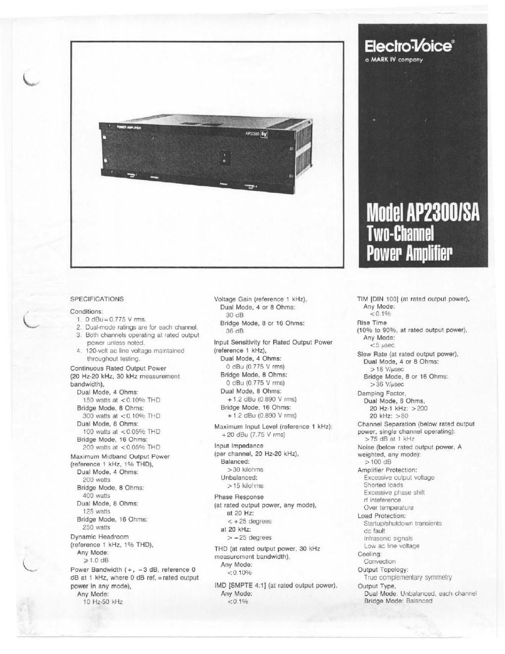
Electro voice ap 2300 sa brochure

This is the 4 pages manual for electro voice ap 2300 sa brochure.
Read or download the pdf for free. If you want to contribute, please mail your pdfs to info@audioservicemanuals.com.

Page: 1 / 4
left right
electro voice ap 2300 sa brochure

Extracted text from electro voice ap 2300 sa brochure (Ocr-read)


Page 2

Output Devices (8. both channels).

Pom: 150 waits

to: 15 A dc

Voeo: 200 V dc

Tim-,2 150°C (302°F)

Controls and Switches.

Input Level Controls (Mm-Rear:
Continuously variable (AP2300)
Stepped attenuators (APQSOOSA)

Dual/bridged mode ewitclHear

Power ewltch-tront
Front-Panel Indicators:

Power LED

Clip LED's (two)

Protect LED's (two)

Connections.

input:
6-ieirninai barrier strip
Female XLR-type connectors (two)
Octal accessory sockets (two)

Output:
4-terminal barrier strip

Power:
3~terrninal IEC ac line receptacle

Power Requirements:

100. 120. 200. 240 V ac.

50/60 Hz. 560 watts at 120 V ac
Power Consumption/Heat Produced (both
channels operating dual mode with 1 kHz
input signal at stated output power Into 4
ohms. or bridge mode lmo 8 ohms).

V3 Power:

560 watts/1.48 kBTU/hr

Fluted Power:

750 watts/1.54 kBTUIhr

Maximum Midband Power:

350 watts/1.56 kBTUlhr
Operating Temperature Flange:

Up to 60 degrees C

(140 degrees F) ambient
Dimensions.

Height: 13.3 cm (5.25 in.)

Width: 43.3 cm (19 in.)

Depth: 27.9 cm (11 in.)

Color:

Black
Enclosure:

Rack mount chaste

16-GA steel bottom/Sides

IB~GA steel lop/back

Virinch 60617T6 aluminum front panel
Shipping Weight:

l6.3 kg (36 lb)

Net Weight:

14.5 kg (32 lb)
Supplied Item:

One owner's manual

One detachable power cord

Four " " jumper plugs tor octai sockets
Optional Accessories:

The octal sockets permit a variety oi plug-

in accessories to be used With the amplifier.

The oplnns are listed below.
APM-i Bridging input translormer
APM-2 Bridging input tiarslorrner with pad
APL-125 low pass module, 125 Hz
APL-SOO low pass module. 500 Hz
APL-BOO low pass module. 800 Hz

APL71250 low DES module. 1250 Hz
APH-125 high pass module. 125 Hz
APH315 high pass module. 315 Hz
APH-SOO high pass medulla, 500 Hz
APH-BOO high pass module. 800 Hz
APH-t250 high pass module. 1250 Hz
APX twoway crossover module.
24 tie/octave. freq. selectable
50 Hz~10 kHz
APX-2 crossover module. as APX with
separate high-pass output tor
other amplifiers
CXI twovway crossover module. 24 dB
octave. widtaeieotaue highirequency
attenuation and 500 or 800 Hz
crossover. raststive selectable
other crossover IrequenCies. and
choice oi modules tor horn EO and
lovv-Irequency time delay
Four output impedance matching
devices are available.
TR150 tsuwatt 70-volt line translormer
TRJOO GOO-watt 70Avoli line translormer
ATVSOO SOC-watt nul'rtap auto-translom'ier
AT-tOD 100w mulHap autoitrarslormer

iNSTALLATION
Unpacking
Upon receipt oi the unit. inspect the shipping
carton tor posstble damage during trans. ll
dairiage is Iound. notily the transportation
company immediately. Should damage occur
during shipping. it is the responsibility at the
consignee to Initiate a claim With the carrier,
"' CAUTION '
No user servimabla parts inside.
Hazardous voltage and currents may be
encountered within the chassis. The
service information contained within this
document is tor use only by ElectroVoice.
Inc.. authorized warranty stations and
qualified service personnel. To avoid
electric shock. do not perform any servic-
Ing unless you are qualified to do so.

DESCRIPTION

The AP2300 and AP23OOSA are dual-
diannel power amplifiers tor prolesstonai
sound reinlcicernent.

The APZSOOSA teatures stepped attenuators
that are calibrated in l-dB steps lrom O to 20
dB attenuation. 2-dB steps Irorn 20 to 30 dB
attenuation and 3GB steps Icr attenuation
beyond 30 dB. The AP2300 uses con-
tinuously variable attenuators The two units
are identical in all other respects

Each channel delivers 100 watts oi
continuous average power into 8 ohms or
150 watts into 4 ohms over lull audio
Irequency range In die bridge mode. the
amplilier can deliver more than 300 walls at
less than 0.10% THD.

Each channel is independently protected
against . . .

- Over temperature

v Excesswe output voltage

I Excessive phase shift

- Radioirequency interierence

' Shorted loads

The load is protected from stamp/shutdown
transients. intrasonic Signals. low ac line
voltage. and do. When a problem is

detected. an output relay automatically
disconnects the load Item the channel and
illuminates the Protect LED located on the
tram panel

The APZSDO has electronically balanced
inputs and accessory sockets lor plug-in
translorrnars and electronic modules. The
level controls are rear mounted to avoid
accidental changes, The universal power
transformer permits 100. 120. 200-. 220.
and 240V 50/60 Hz ac operation. The
EteotroVolce AP2300 power amplitier is tha
chorce for serious prolessional instaliaiiois
which demand the highest quality at high
power levels lot extended periods cl time

ARCHITECTS' AND ENGINEERS'
SPECIFICATIONS

The power ampliiiei shall be a dual-channel
model oi solidrstate desgn employing ime
complementary-symmetry output crrcunry
and capable at operating train a
im/120I200I220I240-V. SOIGO-HZ ac line
The ampliiier shall contain sensrng Circuitry
to provtde protection tor the output tran-
sistors against over temperature. excesswe
output voltage, radio-Irequency interlerence.
shorted loads. and excesswe output phase
shill The load shall be similarly protected
against intrasonic Signals. startuplshutdown
tranSients, low ac line voltage. and dc

Rear-mounted panel controls shall include a
two-posllIOfl mode sWitch tor selecting
between the dual monophonic mode or the
bridged monophonic mode. and indiwduai
input level contiols. Input connections tor
each channel shall include an octal socket
tor use with an optional plug-in input bridgi
ing transtormer or electronic accessory
modules, 3 3pm female XLR-type connector.
and a barrier-strip connector Output
terminals shalt be a bainerslrip connector,

Front panel indicators shall include an
illuminated power on/olt indicator. individually
illuminated clipping indicators (Clip). and
individually illuminated prctadion~clrcuit-
activation indicators (Protect) The iront panel
control shall be the power onloll swnch.

The power amplilier shall meet the iollowtng
pedormance criteria. Maximum input voltage:
7,75 V rnis. Input voltage tor rated output
power into 4 ohms: 0.775 rms. Plated output
power channel. 150 watts into 4 ohms lrom
20 Hz to 20 kHz at less than 010% THD.
100 watts into 8 ohms irorn 20 Hz to 20 kHz
at less than 0.05% THD. 300 watts into
Bohm bridged load Irom 20 Hz to 20 kHz at
less than 0 10% THD with channel ill

driven Voltage amplication in dual mode 30
dB. Hum and noise. at least 100 dB

(A weighted) below rated output power
Frequency response 20 Hz to 20 kHz. 2 1
dB at any output power up to rated output
power. Damping iactor greater than 200 at
any ire-quency up to t kHz in dual mode
With Bohm load

'The mower. ms-on shall hale calibrated stepped
attenuators la input lei/9 wnlloi