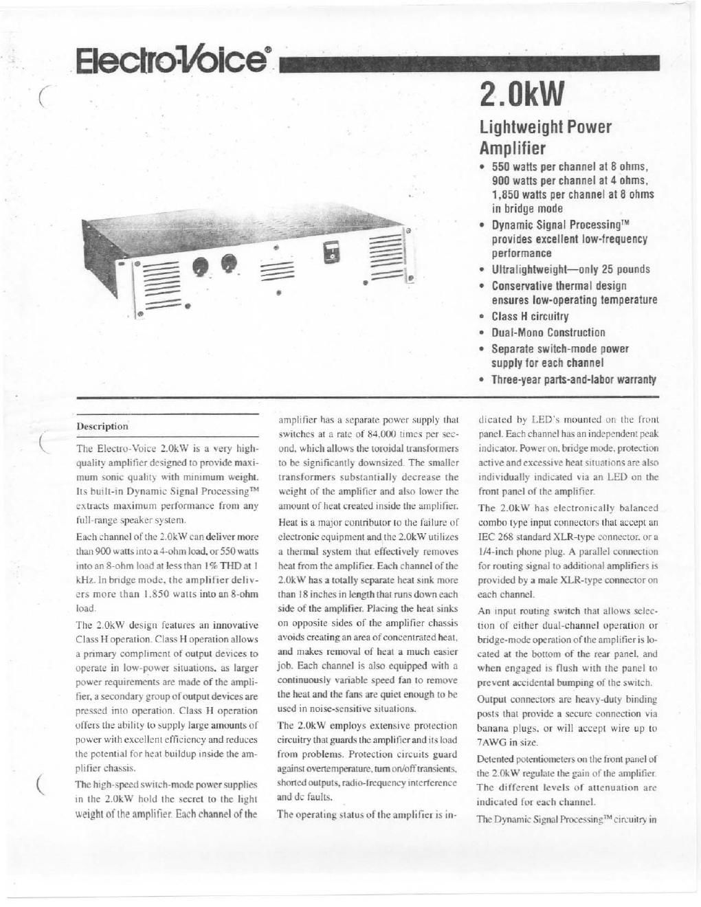
Electro voice 2 0 kw brochure

This is the 4 pages manual for electro voice 2 0 kw brochure.
Read or download the pdf for free. If you want to contribute, please mail your pdfs to info@audioservicemanuals.com.

Page: 1 / 4
left right
electro voice 2 0 kw brochure

Extracted text from electro voice 2 0 kw brochure (Ocr-read)


Page 1

. Electrotbice -

2.0kW

Lightweight Power

Amplifier

- 550 watts per channel at 8 ohms.
900 watts per channel at 4 ohms.
1.850 watts per channel at it ohms
in bridge mode

0 Dynamic Signal ProcessingI
provides excellent low-frequency
performance

- Ultralightweight-only 25 pounds

0 Conservative thermal design
ensures low-operating temperature

- Class H circuitry

- Dual-Mono Construction

0 Separate switch-mode power
supply for each channel

0 Three-year pans-anil-lafior warranty

Des: ription

The Electro-Vutce '.'.0kW is a very high-
quality amplifier designed to provide maxi-
mum sonic quality Wllh minimum weight.
its hurlt-in Dynamic Signal Processing"M
extracts maximum performance from any
ltill»range speaker system.

Each channel of the 2.0kW can deliver more
than 900 watts into a 4-ohm load. or 550 watts
into an S-ohm load at less than I% THD at l
kHz. in hndge mode. the amplifier deliv-
ers more than LSSO watts intoan 8-ohm
load.

The 2.0kW design features an innovative
Class H operation. Class H operation allows
a primary compliment of output devices to
operate in low-poster situations. as larger
power requirements are made of the ampli-
fier. a secondary group of output devices are
pressed into operation. Class H operation
offers the ability to supply large amounts of
power with excellent efficiency and reduces
the potential for heat buildup inside the am-
plifier chassrs.

The high-speed swttch-modc power supplies
tn the lllkW hold the secret to the light
weight of the amplifier. Each channel of the

amplifier has a separate power supply that
swrtchcs at a rate of 84.000 times per sec-
ond. which allows the toroidal transformers
to be significantly downsized The smaller
transformers substantially decrease the
weight of the amplifier and also lower the
amount of heat created inside the amplifier.
Heat is a major contributor to the failure of
electronic equipment and the 2.0kW LlllllLeS
a thermal system that effectively removes
heat from the amplifier. Each channel of the
2.0kW has a totally separate heat stnk more
than [8 inches in length that runs down each
side of the amplifier. Placing the heat sinks
on opposite sides of the amplifier chassis
avoids creating an area of concentrated heat.
and makes removal of heat a much easier
job. Each channel is also equipped with a
continuously variable speed fan to remove
the heat and the fans are quiet enough to he
used in noise-sensitive situations.

The 2.0kW employs extensive protection
circuitry that guards the amplifier and its load
from problems. Protection circuits guard
against ovcttentperature. tum ort/ofi'transienls.
shorted outputs. radio-frequency interterence
and dc faults.

The operating status olthe amplifier Is in-

dicated by LED's mounted on the front
panel. Each channel has an independent peak
indicator. Power on. bridge mode. protection
active and excesstve heat Situations are also
individually indicated via an LED on the
front panel of the amplifier.

The 2.0kW has electronically halanced
combo type input connectors that accept an
[EC 268 standard XLR-type connector. or a
ll4-inch phone plug. A parallel connection
for routing signal to additional amplifiers is
provided by a male XLR-type connector on
each channel.

An input routing swnch that allows selcu
(ton of either dual-channel operation or
bndgevmode operation of the amplifier is lo-
cated at the bottom of the rear panel. and
when engaged is flush Wlll'l the panel to
prevent accidental bumping of the switch.
Output connectors are heavy-duty hindingy
posts that provide a secure connection via
banana plugs. or will accept wire up to
7AWG in size.

Detented potentiometers on the front panel of
the 2.0kW regulate the gain of the amplifier
The different levels of attenuation are
indicated for each channel

The Dynamic Signal Process'ing circuitry in

Page 2

2.0kW Lightweight Power Amplifier

all kW Series amplifiers sets their performance
iipurt front other lightweight amplifiers. 'lwo
watches on the rear of the amplifier select
the mode of operation of the processor and
a pole frequency that should be matched to
the tuning ofa speaker system. This innova-
tive circuitry ensures that the transrenl re-
sponse (it it speaker systems low-frequency
dn \er is accurately controlled and any phase
distortion is minimized. The three settings
available are LPN. Bo and Off. The LPN
setting is used for compact. vented speaker
systems other lltan those manufactured by
Electru-Voice. It is a second-order shelving
equalizer with a pole frequency of 50 Ht.
The B6 setting is specifically for Electro-
Vmce speaker systems and supplies a 6 dB
boost at the selected pole frequency that is
flawlessly combined with an undamped
second-order hightpass filter to provide
matimum low-frequency impact and intra-
sonic protection. The Bo selling ofiers three
different peakvhoost frequencies: 26 Hz. 43 Hz
and 60 Hz. The box tuning frequency of a
speaker system determines which pole tre~
quency is appropriate

The 2.0kw has been evaluated and tested to
applicable ANSI/UL and CSA standards for
use in the US. and Canada The NKl'lJC mark
adjacent to the CSA mark Signifies the prod-
uct meets applicable standards in the US. and
Canada.

The 25~pound Electro-Voice 2.0kW delivers
professional-quality amplification. bong-
tcrrn reliability and maximum portability
make this amplifier the foremost chmce
among mobile sound professionals.

Architects and Engineers'
Specifications

The power amplifier shall be a dualAchannel
model ofsolid-stati: design employing high-
powcr output devices in a true-complimentary-
symmetry output circuit. It shall be capable of
operating from a [20 V. 60 Hz or 220/240 V.
50 HI ac line.

The amplifier shall contain sensing circuitry
to provrde protection tor the output transisi
tors against overtempcrature. excessive out-
put voltagc. radio-frequency interference.
shorted loads and excessive phase shift. The

Lighrvvo .

load shall be similarly protected against start V

uplshutdown transients. low ac line voltage.
and dc.

The power amplifier shall contain pmcesstng
Circuitry that Will ameliorate the phase and
transient response problems of the loud-
speaker. The built-in processor shall be ca-
pable ofbeing adjusted for the enclosure type
and low-frequency characteristics of the
connected speaker.

Rear-mounted panel controls shall include
an input routing switch for selecting dual/
stereo or parallel mono operation and two
switches for control of the processor. The
processor controls shall include a switch for
luming the processor off and selecting the
enclosure type and three selectable frequen-
cies for B6 alignment of 60 Ht. 43 HI. and
26 Hz.

Front-panel indicators shall include power
on. peak. overtemperature. protect active.
and bridge-mode. Front-panel controls shall
include a power switch and level controls
that shall he dctented potentiometers with
accurate markings.

The power amplifier shall meet the follow-
ing performance specifications: maximum
input voltage. 7.75 V nns; input voltage for
rated output power into 4 ohms. shall be
.74 V rtns. rated output power per channel.
greater than 700 watts into 4 ohms from
20 Hz to 20 kHz at less than 0.!0 THD.
greater than 450 watts into 8 ohms from
20 Hz to 20 kHz at less than 0J0 THD.
greater than 1.400 walls into an 8 ohm
bridged load from 20 Hz to 20 mt at less
than 0.I07r THD: hum and noise shall be
greater than l00 dB (A weighted) below
rated output power: frequency response
shall be 12 to mkHz. +Ol-3 dBr. any mode.
at any output power up to rated output power;
damping factor shall be greater than 200 at
any frequency up to I kit! in dual mode with
an 8 ohm load; intennodulation disloflton
(SMP'TE) shall be less than 0.05% at mled
power in any mode into 8 ohms: operating
temperature shall he up to 50 C ambient:
channel separation shall he greaterthan 50 dB.
Dimensions shall be (H x W x D): 88.9 mm
(3.5 in.) x 482.6 mm (19 in.) x 469.9 mm

8.5 in.). Net weight shall he .33 kg (15
lb). Color. dark gray With White nomencla-
ture.

The 2.0kW has been evaluated and tested to
applicable ANSI/UL and CSA standards for
use in the U.S. andCtutada The NlU'UC mark
adjacent to the CSA mark signifies the prod-
uct meets applicable standards in the U S and
Canada

The power amplifier shall he the
Electro-Vorce 2 0kW.

Unifonn Limited Warranty Statement

Elcctro-Voice products are guaranteed
against malfunction due to detects in mate-
rials or workmanship for a specified pcnod,
as noted in the inditidual product-line
statementts) below. or in the indmdual prod
uct data sheet or owners manual. beginning
With the date of original purchase. if such
malfunction occurs during the specified pe-
riod. the product will be repaired or replaced
tat our option) without charge. The product
Will be returned to the customer prepaid
Exclusions and Limitations: The Limited
Warranty does not apply to: tat extenor fitt-
ish or appearance: tb) cenain specific items
described in the individual product-line
statemenl(s) below. or in the individual prod-
uct data sheet or owners manual; tct mal-
function resulting from use or operation of
the product other than as specified in the
product data sheet or owners manual: tdi
malfunction resulting from misuse or abuse
of the product, or (c) malfunction occumng
at any time after repairs have been made to
the product by anyone other than EVI Au~
dio Service or any of its authorized service
representatives. Obtaining Warranty Ser-
vice: To obtain warranty service. a customer
must deliver the product. prepaid. to 13V]
Audio Service or any of its authorized scrr
vice representatives together with proof of
purchase of the product in the form of a hill
of sale or receipted invoice. A list of autho-
rized service representatives is available front
EVI Audio Service at 000 Cecil Street.
Buchanan. M149I07 {800/234-6243 I or FAX
bio/6954743). Incidental and Conse-
quential Damaga Excluded: Product rer
pair or replacement and return to the cus
tomcr are the only remedies provided to the