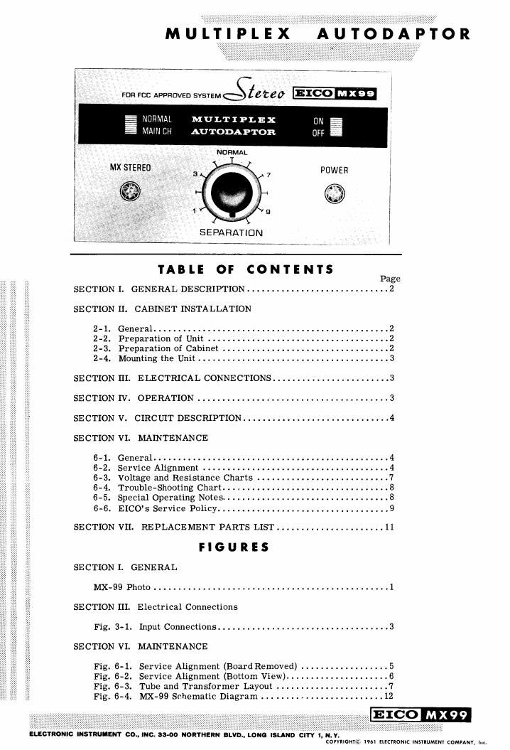
Eico MX 99 Owners Manual

This is the 12 pages manual for Eico MX 99 Owners Manual.
Read or download the pdf for free. If you want to contribute, please mail your pdfs to info@audioservicemanuals.com.

Page: 1 / 12
left right
Eico MX 99 Owners Manual

Extracted text from Eico MX 99 Owners Manual (Ocr-read)


Page 1

MUIITIHPL'EX' AHUTODAHPITOR

Fm FCC APPROVED svsvemététeD

NORMAL MULTIPLEX
MAW CH AUTODAPTOR

NORMAL

TABLE OF CONTENTS

Page
SECTION I. GENERAL DESCRIPTION ............................. 2
SECTION H. CABINET INSTALLATION
2-1. General ................................................ 2

2-2. Preparation of Unit . . . .
2-3. Preparation of Cabinet .

2-4. Mountingthe Umt3
SECTION III. ELECTRICAL CONNECTIONS ........................ 3
SECTION IV. OPERATION ....................................... 3
SECTION V. CIRCUIT DESCRIPTION .............................. 4

SECTION VI. MAINTENANCE

. General ................................................
. Service Alignment ............
. Voltage and Resistance Charts . . .
. Trouble-Shooting Chart. .....


mOHInmo:
unknown
mmqtbux


- . Special Operating Notes. . .

6-6. EICO's Service Policy ................................... 9

SECTION VII. REPLACEMENT PARTS LIST ...................... 11
F I G U R E 5

SECTION I. GENERAL

MX~99 Photo ................................................ 1
SECTION III. Electrical Connections

Fig. 3-1. Input Connections ................................... 3
SECTION VI. MAINTENANCE

Fig. 6-1. Service Alignment (BoardRemoved) .................. 5

Fig. 6-2. Service Alignment (Bottom View). . . . . 6

Fig. 6-3. Tube and Transformer Layout . . . . .7

Fig. 6-4. NIX-99 Schematic Diagram ......................... 12

EL OYRONIC INSTRUMENT CD.. INC. 88-00 NORTNERN BLVD.. LONG ISLAND 0""! 1I N. V.

cormcn U 1961 ELEcnomc INsnuMsNr coMrANY. Inn

Page 2

PAGE 2

INSTRUCTION BOOK

SECTION I. GENERAL DESCRIPTION

The new EICO NIX-99 Multiplex Autodaptor*employs
an original method of zero phase shift, filterless detec-
tion of multiplexed signals. The unit automatically
delivers stereo on a stereobroadcast signal, and mono
from a mono signal without spurious signals in either
case. The stereo signal is automatically gain-balanced
and the mono signal is automatically equal from both
outputs without adjustment. An indicator lamp turns
on when the station selected is broadcasting multiplex
stereo.

The design features freedomfrom phase distorting
filters in either the main or sub channel paths which
cause loss of separation. Nevertheless this design
provides the required, or better-than-required, sup-
pression of all spurious signals including SCA (67kc)
background music carrier, reinserted 38kt: sub-car-
rier, 19kc pilot carrier, and all harmonics thereof.
This is achieved partly through an original technique
for deriving the left and right signals, and partly by
sharp ultrasonic filters after the signals are derived.
All of the foregoing is very important for high quality
tape recording, where spurious signals can beat against
the tape recorder bias oscillator and result in audible
spurious tones in a recording. This adaptor will syn-
chronize with any usable output from the FM tuner
and will demodulate without significant distortion tuner
(composite signal) as high as 5 volts peak-to-peak.

The MX-99 is self powered, and includes low
impedance cathode follower outputs. External controls
include an oscillator turn-off switch to permit inter-
ference-free listening to mono stations having low
sub-carrier frequency SCA store-casting anda separ-
ation control. A separation of 30db between channels
is typical and an overall gain of unity is provided from
input to output on both stereo and mono. The MXv99
is designedfor all EICO FM equipment (HFT90, HFT92,
ST96), and any other component quality, wide band FM
tuner provided with a multiplex output.

Tubes: 2-12AU7, 1-12AT7, I-GAUG, 1-6D10, 1-6X4

and 6 diodes
Size (HWD): 3-7/8" x 9-1/8" x 6-3/8"
Weight: 7 lbs.
Cover: OPTIONAL
*Patent Pending
SECTION II. CABINET INSTALLATION
2-1. GENERAL

1. Mount horizontally on awell-braced shelf. The
stock thickness of the wood panel may not exceed 3/4".

2. Do not remove feet for mounting. Air must be
allowed to enter through the perforations inthe bottom
plate to avoid overheating.

3. To avoid over heating when stacking components
mount the tuner below the amplifier with the NIX-99
alongside the tuner. Any shelf above the MX-99 must
be spaced at least 2 inches away. Allow at least a 1-
inch tolerance on either side of the unit.

4. Leave the back of the cabinet entirely open.

2-2. PREPARATION OF UNIT

1.. Loosen the left and right side pairs of screws
(4 in all) that fasten the bottom plate and cover to the
chassis, just enough to permit the cover and bottom
plate to slide backward or forward in the 3/4" chassis
slots.

2. Push both cover and bottom plate back as far
as they will go (3/4"). The screws that have been
loosened will move from the front to the rear ends of
the slots in the chassis.

3. Detach the knob from the separation control
shaft. Then remove theZ screws, that fasten the panel
to the chassis, one at the left of the NORMAL-MAIN
CH switch and the other at the right of the ON-OFF
switch. Take panel off and set it aside. The unit is
now prepared for cabinet installation.

2-3. PREPARATION OF CABINET

1. Two templates are provided, one for the cabinet
shelf and the other for the cabinet panel. The shelf
template is used to locate exactly two holes that are
to be drilled in the shelf. The panel template is used
to locate exactlythe required rectangular cut-out. The
two templates must be used together as indicated, as
there is an exact relationship between the locations of
the shelf holes and panel cut-out.

2. To use the shelf template, cut it or fold it back
exactly along the dashed line. Remove the shelf from
the cabinet and line up this dashed line on the template
with the front edge of the shelf, positioning it also along
the edge to leave at least 1 clearance on each side.
Tape the template in position and use a center punch
to mark the centers of the two holes to be drilled. If
the shelf can not be removed, place the template in a
similar manner on the top side of the shelf if there is
room to drill from the top side, or on the under side
of shelf if there is room only to drill from the under
side. If the template is used on the underside of the
shelf, mark the rear edge of the shelf at the points
where the extended heavy lines on the template hit the
rear shelf edge. After the holes are center-punched,
remove the template and drill carefully through the
punched centers to a diameter of 1/4". If the shelf
has been removed for the drilling operation, now re-
mount it. Finally, replace the shelf-template in exactly
its former position on the top-side of the shelf and

Page 11

SECTION VII. REPLACEMENT PARTS LIST

Replacement Parts List (Cont'd.)

SYM.# srocxa AM' T. DESCRIPTION
Cl 22560 1 capacitor, disc, .05mid, GMV (50K or 50,000mmf)
C2 23039 1 capacitor, elec., lmfd, 15V
C3 20063 1 capacitor, mylar, .03mfd, 5%
C4,5 22552 2 capacitor, disc, 220mmf, 10%
C6 23048 1 capacitor, elec., lmfcl, 150V
C7 24005 1 capacitor, elec., 20 x 40 x 40mfd
C8,9,10 22560 3 capacitor, disc, .05mfd, GMV (50K or 50,000mmf)
C11 22532 1 capacitor, disc, .0015mfd, 10% (1.5K or 1500mmf)
-‚¬12,14,16 22560 3 capacitor, disc, .05mfd, GMV (50K or 50,000mmf)
C13 22532 1 capacitor, disc, .0015mfd, 10% (1.5K or 1500mmf)
C15 23500 1 capacitor, e1ec., 10mfd, 12V
C17 22548 1 capacitor, disc, .009mfd, 10% (9K or 9000mmf)
C18,19 20062 2 capacitor, mylar, .025mid, 10% (25K or 25, OOOmmf)
C20 22548 1 capacitor, disc, .009mfd, 10% (9K or 9000mmf)
021,22 20062 2 capacitor, mylar, .025mfd, 10% (25K or 25, 000mmf)
C23,24 23015 2 capacitor, elec., 50mm, 150V
C25 22521 1 capacitor, disc, .001mfd, 10% (1K or 1000mmf)
CR1,2,3,4,5,6 95006 6 diode, 40v, PIV
Fl 91002 1 fuse, 1 Amp
11,2 92012 2 bulb, NE-ZE
J1 50014 1 jack, single
J2-3 50011 1 jack, dual
L1,2 35068 2 coil, 8mh
R1 10453 1 resistor, 18K ohm, 10%, 1/2W (brown,grey,orange,silver)
R2 10434 1 resistor, 2.2M ohm, 10%, 1/2W (red,red,green,silver)
R3 10446 1 resistor, 270 ohm, 10%, 1/2W (red,violet,brown,silver)
R4 10450 1 resistor, 3900 ohm, 10%, 1/2W (orange,white,red,silver)
R5 10435 1 resistor, 150K ohm, 10%, 1/2W (brown,green,yellow,silver)
R6 10441 1 resistor, 150 ohm, 10%, 1/2W (brown,green,brown,silver)
R7 10431 1 resistor, 470K ohm, 10%, 1/2W (yellow,violet,yellow,silver)
R8 10407 1 resistor, 1M ohm, 10%, 1/2W (brown, b1ack,green,silver)
R9,10 10410 2 resistor, 100K ohm, 10%, 1/2W (broum,black,yellow,silver)
R11 10442 1 resistor, 1500 ohm, 10%, 1/2W (brown,green,red,silver)
R12,13,14,15, 11068 6 resistor, 1500 ohm, 1%, l/ZW
16,17
R18 10426 1 resistor, 33K ohm, 10%, 1/2W (orange,orange,orange,silver)
R19,20 14505 2 resistor, 3000 ohm, 10%, SW
R21 10434 1 resistor, 2.2M ohm, 10%, 1/2W (red,red,green,silver)
R22 11038 1 resistor, 9000 ohm, 1%, 1/2W
R23 10442 1 resistor, 1500 ohm, 10%, 1/2W (brown,green,red,silver)
R24 11018 1 resistor, 9500 ohm, 1%, 1/2W
R25 11079 1 resistor, 100K ohm, 1%, 1/2W
R26,27,28,29 11020 4 resistor, 40K ohm, 1%, 1/2W
R30 11079 1 resistor, 100K ohm, 1%, l/2W
R31 18091 1 potentiometer, 250K ohm, linear, taper
R32 11079 1 resistor, 100K ohm, 1%, 1/2W
R33 10426 1 resistor, 33K ohm, 10%, 1/2W (orange,orange,orange,silver)
R34 10442 1 resistor, 1500 ohm, 10%, 1/2W (brown,green,red,silver)
R35 10435 1 resistor, 150K ohm, 10%,1/2W (brown, green, yellow, silver)
R36 11049 1 resistor, 70K Ohm, 1%, 1/2W
R37 10434 1 resistor, 2.2M ohm, 10%, 1/2W (red,red,green,silver)
R38 10407 1 resistor, 1M ohm, 10%, 1/2W (brown,black,green,silver)
R39 11559 1 resistor, 12K ohm, 5%, 1/2W (brown,red,orange,gold)
R40 10528 1 resistor, 270 ohm, 5%, l/ZW (red,violet,brown,gold)
R41 11051 1 resistor, 10K ohm, 1%, 1/2W
R42 10407 1 resistor, 1M ohm, 10%, l/2W (brown, black,green,silver)
R43 10446 1 resistor, 270 ohm, 10%, 1/2W (red,violet,brown,silver)
R44,45 10413 2 resistor, 2700 ohm, 10%, l/ZW (red,violet,red,silver)
R46 10446 1 resistor, 270 ohm, 10%, 1/2W (red,violet,brown,silver)
R47,48 10453 2 resistor, 18K ohm. 10%, 1/2W (brown,grev,orange,silver)

SYM.# STOCK# AM' T. DESCRIPTION
51,2 62015 2 switch, slide, SPST
T1 30056 1 transformer, power
T2 34631 1 coil, filter, 19kc
T3 34632 1 coil, doubler, 19kc
T4 34633 1 coil, oscillator, 38kc
T5 33001 1 coil, trap, 67kc
TB] 54018 1 terminal strip, 4 post, with ground
TB2 54015 1 terminal strip, 3 post 2 left, with ground
TBS 54006 1 terminal strip, 3 post, 2 right
T134 54018 1 terminal strip, 4 post,with ground
T135 54024 1 terminal strip, 2 post, left
T136 54044 1 terminal strip, 3 post left, with ground
V1 90012 1 tube, 12AT7
V2 90033 1 tube, 12AU7
V3 90081 1 tube, 6D10
V4 90020 1 tube, 6AU6
V5 90033 1 tube, 12AU7
V6 90036 1 tube, 6X4
XFl 97800 1 fuseholder
XVl 97025 1 tube, socket, 9 pin miniature, bottom mount
XVZ 97065 1 tube, socket, 9 pin with shield
XV3 97064 1 tube, socket, 12 pin, compactron
XV4 97022 1 tube, socket, 7 pin miniature, bottom mount
XV5 97065 1 tube, socket, 9 pin with shield
XVG 97022 1 tube, socket, 7 pin miniature, bottom mount
40000 10 nut, hex, No. 6-32
40001 1 nut, hex, 3/8-32
40007 18 nut, hex, No. 4-40
40016 1 nut, 1/2", fuseholder
40017 6 nut, Tinnerman, No. 8-82
40034 4 nut, Tinnerman, No. 4-40
41046 4 screw, No. 8-32 x 3/8, brown
41086 10 screw, No. 6-32 x 5/16
41090 12 screw, No. 4-40 x 5/16
41091 4 screw, No. 4-40 x 1/4, flat head
41097 2 screw, No. 6-32 x 5/ 16, brown
41110 6 screw, No. 4-40 x 1-1/8
42000 1 washer, lock, 3/8"
42001 1 washer, flat, 3/8"
42002 10 washer, lock, No. 6
42007 24 washer, lock, No. 4
42029 1 washer, rubber, 1/2"
42039 6 washer, flat, No. 4
44020 6 spacer, 3/4"
46015 4 foot, plastic
51503 2 clip, can
53049 1 knob
57000 1 line cord, brown
80122 1 panel
81333 1 chassis
81334 1 bottom plate
81335 1 cover (OPTIONAL)
81955 1 bracket, coil
82101 1 strain relief
82509* I printed board
89261 1 label, nomenclature, back
89262 1 label, tube layout
89627 1 capsule, glue
89684 2 bulb, housing, fishpaper
97304 2 shield for slide switch
97720 2 jewel
66106 1 manual of instruction (wired)
66359 1 manual of instruction (kit)
*82512 and 82509 are interchangeable

PAGE 11