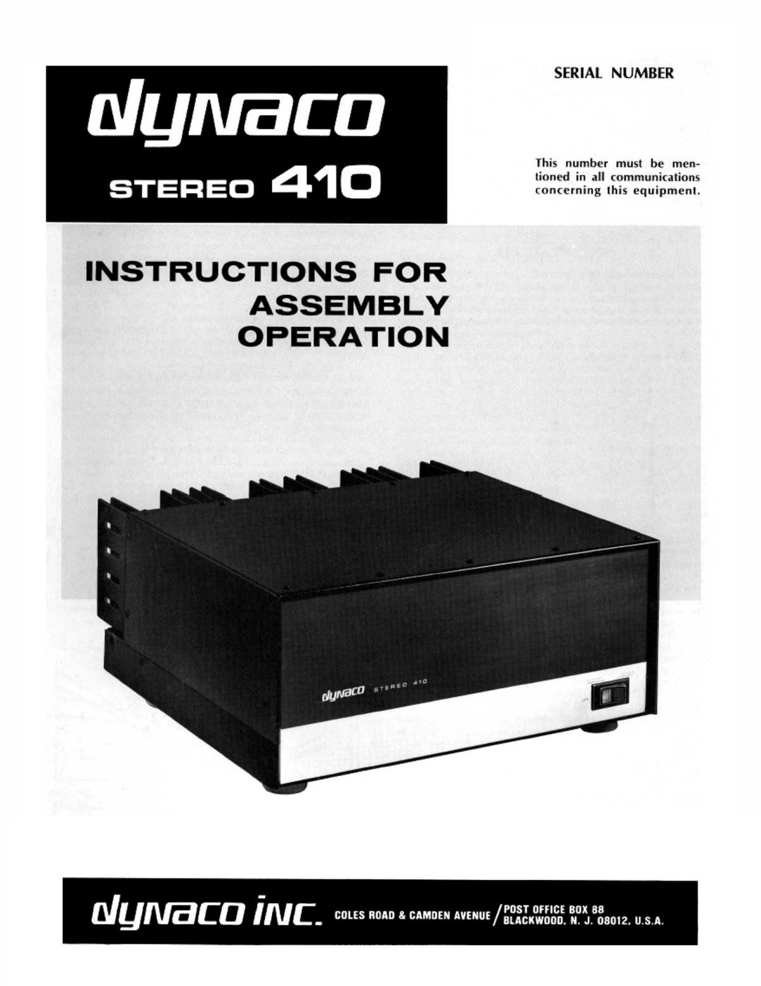
Dynaco Stereo 410 Owners Manual

This is the 25 pages manual for Dynaco Stereo 410 Owners Manual.
Read or download the pdf for free. If you want to contribute, please mail your pdfs to info@audioservicemanuals.com.

Page: 1 / 25
left right
Dynaco Stereo 410 Owners Manual

Extracted text from Dynaco Stereo 410 Owners Manual (Ocr-read)


Page 1

SERIAL NUMBER

Nymaca

This number must be men-

lioned in all communications
STEREO 41 0 concerning this equipment.

INSTRUCTIONS FOR

ASSEMBLY
OPERATION

POST OFFICE BOX 88
ulymaca INC. /...J.

Page 2

CONTENTS

Specifications . . . . ...... . . ...... . 2
Introduction .......... 3
Installation ....... 3
Connections .......... . 3
Operation . ............ . ..... . . . 4
Assembly Instructions . . . . . . . . . .. . 5
Mechanical Assembly ........ . . 7
WiringtheChassis............. 9
Wiring P040 . ............. . . . 10
Wiring the Heat Sink ........... 11
Final Assembly . ............. . . 17
SPECIFICATIONS

Power output ratings:

Less than 0.25% total harmonic distortion at any power level up to
200 watts continuous average power per channel into 8 ohms (100
watts per channel into 16 ohms) at any frequency between 20 Hz and
20 kHz with both channels driven. Distortion reduces at lower power
levels.

Available power output:

(See above for F.T.C. Power Ratings}

20 Hz to 20 kHz, both channels driven:
200 watts continuous average per channel @ 8 ohms.
300 watts continuous average per channel @ 4 ohms.'
100 watts continuous average per channel @ 16 ohms.

4 minute sustained full power limit.

Interrnodulation distortion:

Less than 0.1% at any power level up to 200 watts rms per channel
into 8 ohms with any combination of test frequencies. Distortion
reduces at lower power levels.

Power at clipping, single channel, 2500 Hz, less than 1'1. distortion:

235 watts @ 0 ohms.
350 watts @ 4 ohms.
135 watts @ 16 ohms.

Hall-power bandwidth:
100 watts per channel at less than 0.25% total harmonic distortion
from 5 Hz to 35 kHz into 8 ohms.

Frequency response:
+0, --1 d8, 8 Hz-SO kHz @ 1 watt into 8 ohms.
10.5 dB. 20 Hz-20 kHz @ 200 watts.

Hum and noise:

Greater than 95 dB below rated output, full spectrum. Greater than
100 dB below rated output, 20 Hz-20 kHz.

Input:
20,000 ohm load; 1.6 volts for 200 watts @ 8 ohms.

Slewing rate:
8 volts per microsecond.

Damping factor:

Greater than 80 to 1 kHz into 8 ohms.
Greater than 30 to 10 kHz into 8 ohms.

Channel separation:
Greater than 60 dB by IHF standards.

Connectors:

Inputs: phono jacks. Outputs: color coded 3-way binding posts wrth
standard 'II spacing.

Bob01605@aol.com

2

Schematic Diagram 12
ComponentValues 13
CircultDescription 14
Block Diagram ....... 15
MeterOption 20
InCaseofDilficulty ....... .. 20
Voltages . ..... . ..... . ....... 21-22
Circuit Board Layouts 21-22

Service Policy and Limited Warranty 23

KitPansLis nnnnnnnnn IJIIIIIIOI 24
International Transformer Wiring . . . Insert
Pictorial Diagram ....... . . . . . . . . .Inset't
Dimensions:
165/." wide; 14%" deep; 7V4" high.
Weight:

Shipping weight 50 lbs. Net weight 44 lbs.

Power consumption:
120 v.a. quiescent; 11 amps maximum; 50/60 Hz, 120 VAC.

TYPICAL PERFORMANCE CURVES

To arrive at typical curves, four channels were evalu-
ated on all bases. In each case, the curve shown is the next,
to-the-worst of the four. Therefore, do not expect exact cor-

relation between curves.

YMCA]. PWOIIMANCE (his

II I "3 It «It

.I I I I
M -
III

5

g, ----msm. not run

E '\

a

tritium "his. I! 1 III: «Mn (monument mun. Inn

II III (In mo moat
.I l f I r
M _ Io-m In"
3 -Iw III
E . D... II III'TS
'
.0! F
.It -
Ioul thunk Ohm-on hey-rm both duo-eh than I II- III
.I! I "m It I»
.IS I I '
Eu -
§
.. ti

umwomnmmtuhmmmrm-u

Page 18

3t )Preparea 10" (25.5 cm) whitewire. Connectoneend
to power switch lug #4. The other end will be con-
nected later.

4( )Select one of the .01 p! disc capacitors, and cut its
leads to % (1 cm) each. Connect one lead topower
switch lug #4 (3-2). Tuck the capacitor under the
switch, and connect the other lead to power switch
lug #5.

5( )Prepare a 51 " (14 cm) black wire. Connect one end

to power switch lug #1 (S). The other end will be
connected later.
[If the international power transformer is to be installed
and wired for 100 or 120 volts, complete this step as indi-
cated above. If this transformer is to be wired for 200.
220 or 240 volts, prepare instead a 12%" (32 cm) black
wire. Connect one end to power switch lug #1 (S). The
other end will be connected later.]

6( )Prepare a 13 (33 an) blue wire. Connect one end to
power switch lug #5. The other end will be connected
later. [If meters are being installed, refer now to the
M05 instructions before continuing with the next
step]

Set this assembly aside for a moment, and place the
chassis assembly in front of you.

'7( )Select the power transformer, the four 1A" #10 screws,
the four large flat washers, and the four #10
nuts. Mount the transformer on the left front of the
chassis with both sets of transformer leads facing
front. Place a larger washer on top of each trans-
former foot before the nut is installed. Slide the trans-
former over toward the fan as far as it will go, and
firmly tighten the hardware.

When connecting the leads from the power transformer,
you may shorten them appropriately to fit.

8( )Connect the heavy red-yellow transformer lead to
terminal strip T-2 lug #9 at the base (8). Do not
confuse this lead with the two heavy red leads, which
will be called for shortly.

9( )Connect the blue-yellow lead to T-2 lug #9 at the tip.
Do not confuse it with the two blue leads.

10( )Connect the green lead to T2 lug #9 at the tip (8-3) .

11( )Connect either one of the blue leads to T-2 lug #8 at
the base (8).

12( )Connect the other blue lead to T-2 lug #7 at the
base (S).

13( )Iwist the two heavy red leads together. Connect
either one of them to diode block lug #3. Connect the
other red lead to diode block lug #1. You may wish
to solder these two connections now, even though
another lead will be connected to each in the next

step.

l4( )Select the remaining .01 pt disc capacitor, and cut its
leads to =34 (2 cm) each. Strip a 1 (2.5 cm) piece
of insulation from the black wire, and cut the insula-
tion in two equal pieces. Slip a piece of insulation on
each lead of the capacitor. Connect one lead to diode
block lug #3 (8-2). Connect the other lead to diode
block lug #1 (8-2).

18

The next two steps, 15 and 16, describe the wiring for the
primary of the standard power transformer, part #464026.
If instead the international power transformer, part #464030,
is installed, the wiring will differ because of the additional
leads (even if it is to be wired for 120 volts). Instructions
for wiring it will be found on the back of the Pictorial Dia-
gram, and they should be followed in place of the next two
steps.

15( )Connect the heavy black lead to terminal strip T-2
lug #3 at the base (S). Do not confuse this wire with
the heavy black-white lead.

16( )Connect the heavy black-white lead to terminal strip
T-2 lug #1 at the base (S).

Place the front panel assembly adjacent to the front of the
chassis assembly flat against your work surface, positioned
as shown in the Pictorial Diagram. You will now connect
the power switch wires.

17( )Connect the free end of the white wire from power
switch lug #4 to power fuse block lug #1 (S) .

18( )Connect the free end of the yellow wire from power
switch lug #3 to terminal strip T-2 lug #3 at the tip.
[if the international transformer has been installed and
wired for 100 or 120 volts, complete this step as indicated
above. If this transformer is wired for 200. 220 or 240
volts, instead connect the free end of this yellow wire to

lug #3 of the additional 6-lug terminal strip at the tip
(3-2).]

19( )Connect the free end of the black wire from power

switch lug #1 to T-2 lug #1 at the tip.

[If the international transformer has been installed and
wired for 100 or 120 volts, complete this step as indicated
above. If this transformer is wired for 200. 220 or 240
volts. instead connect the free end of this black wire to

lug #5 of the additional 6-lug terminal strip at the tip
(3-2).]

20( )Prepare a 13%" (34 cm) white wire. Connect one
end to T4? lug #1 at the tip (8-2) . Connect the other
end to T-l lug #2 at the tip.

[If the international transformer has been installed and

wired for 100 or 120 volts, complete this step as indicated
above. If this transformer is wired for 200. 220 or 240
volts, do not solder the white wire yet on either end.
Prepare another 9" (23 cm) white wire. Connect one end
of this wire to 'I-2 lug #l at the tip (8-2). Connect the
other end of this wire to lug #4 of the additional 6-lug
terminal strip at the tip (8-2).]

21( )Connect the free end of the blue wire from power
switch lug #5 to T-l lug all at the tip.

22( )Select the back panel assembly, and two 1A" black
self-tapping sheet metal screws. Place the panel in
position at the back edge of the chassis, after bending
the several single leads and the twisted pair away
from the panel at the bottom. Insert the screws only
in the rear most corner hole at each end of the MB.
The screws cut their own thread and therefore some
force is required. Do not tighten the screws com-
pletely so the panel can be tilted out for working.

23( )Select one of the conductors of the line cord. Connect
it to T-l lug #2 at the tip (8-2).

24( )Select the remaining conductor of the line cord. Con-
nect it to power fuse block lug #2 (S) .

Bob01605@aol.com