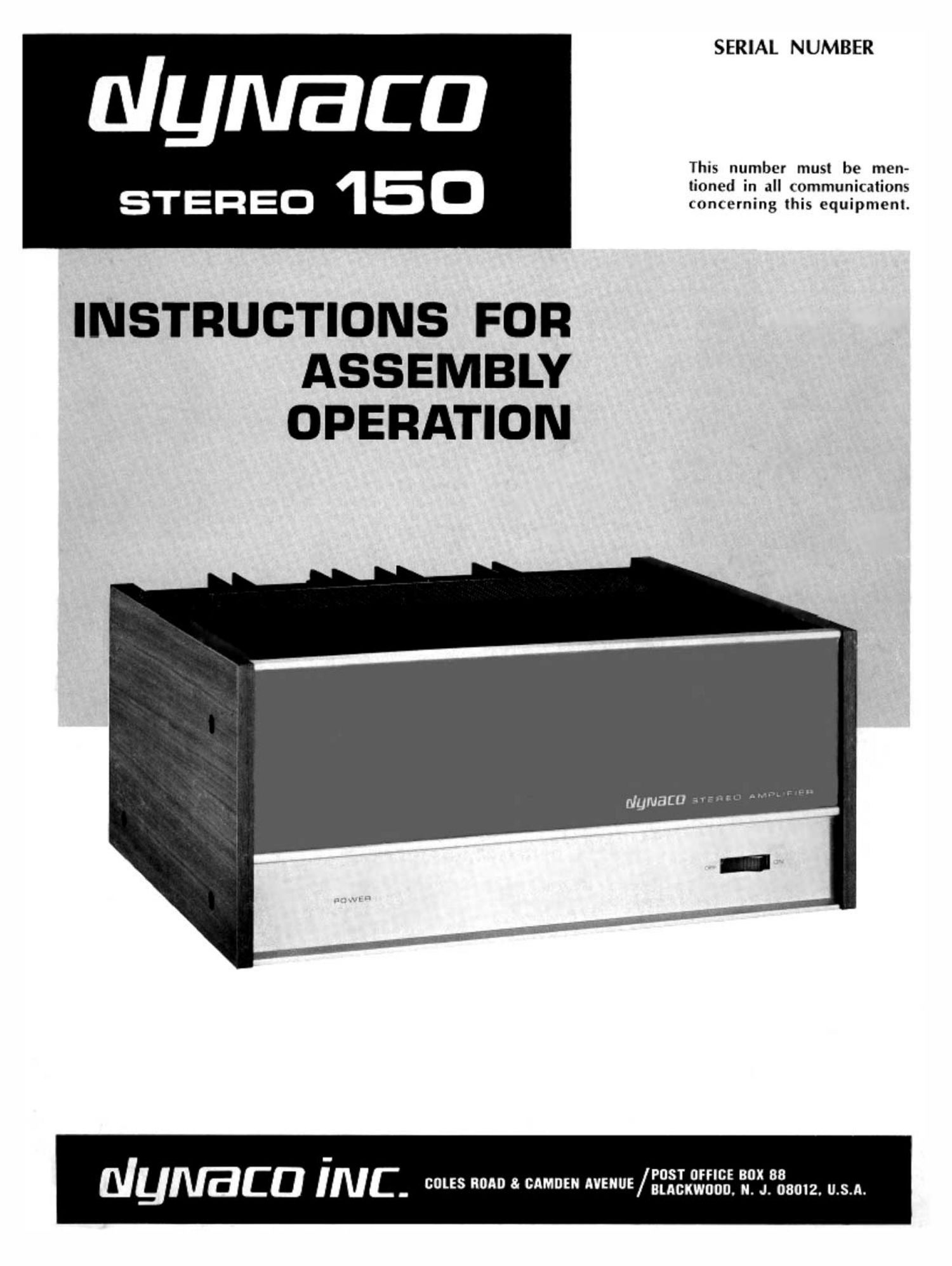
Dynaco Stereo 150 Owners Manual

This is the 24 pages manual for Dynaco Stereo 150 Owners Manual.
Read or download the pdf for free. If you want to contribute, please mail your pdfs to info@audioservicemanuals.com.

Page: 1 / 24
left right
Dynaco Stereo 150 Owners Manual

Extracted text from Dynaco Stereo 150 Owners Manual (Ocr-read)


Page 2

SPECIFICATIONS

Power output ratings:

Less than 025°!» total harmonic distortion at any power level up to 75
watts continuous average power per channel into 8 ohms (40 watts per
channel into 16 ohms, or 150 walls monophonicallv into 8 ohms] at
any frequency between 20 Hz and 20 kHz with both channels driven.
Distortion reduces at lower levels.

Available power output:

(See above for F.T.C. Power Ratings)
20 Hz to 20 kHz, both channels driven:
75 watts continuous average per channel @ 8 ohms,-
100 watts centinuOus average per channel @ 4 ohms;"
40 watts continuous average per channel @ 16 ohms.
nonophonically, 20 Hz to 20 kHz:
150 watts continuous average @ 8 ohms.

" 4 minute sustained full power limit without a fan.

lntermodulation distortion:

Less than 0.25% at any power level up to 75 watts rms per channel
into 8 ohms with any combination of test frequencies. Distortion
reduces at lower power levels.

Power at clipping, single channel, 2500 Hz, less than 1% distortion:

90 watts @ 8 ohms;
t30 watts @ 4 ohms;
45 watts @ 16 ohms.

Halt-power bandwidth:

37.5 watts per channel at less than 0.25% total harmonic distortion
from 5 Hz to 40 kHz into 8 ohms.

Frequency response:
+0, -1 d8, 10 Hz- 40 kHz @ 1 watt into 8 ohms;
20.5 dB, 20 Hz- 20 kHz @ 75 watts

Hunt and noise:
Greater than 95 dB below rated output, full spectrum.

Input:
35,000 ohm load; 1.0 volt for 75 watts @ 8 ohms.

Slewins rate:
5 volts per microsecond.

Damping factor:

Greater than 80 to 1 kHz into 8 ohms;
Greater than 50 to 10 kHz into 8 ohms.

Channel separation:
Greater than 70 dB by lHF standards.

Connectors:

Inputs: phono jacks. Outputs: Color coded 3-way binding posts wrtn
standard It" spacing.

Dimensions:

14%" wide, 13%" deep, 6%" high.
Weight:

Shipping weight 34 lbs; Net weight 29 lbs.

Power consumption:
60 v.a. quiescent; 5 amps maximum 5 50160 Hz, 1201240 vAC.

TYPICAL PERFORMANCE CURVES

To arrive at: typical curves, four channels were evaluated on all bases. In each case, the curve shown is the next-tethe-
worst of the four. Therefore, do not expect exact correlation between curves.

75' loo
1-

M to WATTS l0
I F

N Intermodulotion Distortion vs. Power Output,
Both Channels Driveneohm load


.05

.02

Va 0|S'l0llTl0I


.0'

200 - "Hill 2000 000

Total Hmnonic Distortion vs. Frequency.
Both Channels Driven,80hm loud

FM

Hummus-loll!!!mua.up...""annuluuuumwufle

20

i DISTOIITIOI

- 75 Watts
Human» 7.5 8 .75 Watts

BobO1605@aol.com

Page 4

Two speakers are connected in phase when maximum
low frequency output is heard when they are driven from
a monophonic source. Lowered output is observed when
the connection to one of the speakers is reversed (out of
phase, or reversed polarity). When using multiple speak-
ers on each channel, or with 4-channel systems, it is
important that all of the Speakers in the same area be
wired in phase.

The amplifier terminals are 3-way binding posts which
will accept single or double banana plugs," spade lugs,
or simply stranded wire. If stranded lamp cord is used,
the wire ends should be tinned with solder first to avoid
fraying. To connect the wire, unscrew the terminal cap
until the vertical hole through the metal shaft is uncov-
ered from below, push the wire and through the hole, and
tighten the cap.

Make certain that no wire strands can touch other than
the intended terminal. Double banana plugs (from radio
supply houses) are the most convenient connectors, and
are simply inserted into the ends of the terminals. They
are particularly useful if a second set of speakers is to be
connected in parallel, as they plug into one another.

The black "common output terminals are electrically
connected internally. They are also connected to the
chassis, so the Stereo 150 may be used with special output
connections which require common grounds. You must be
certain that the polarity of such output connections is
never reversed, however, so that the red hot terminals
can never be connected together in other equipment.

AC POWER

The power cord should be plugged into a switched outlet
on a control preamplifier, such as a Dynaco PAT-5, PAT-4
or PAS-3X. Once connected, the Powea switch on the
Stereo 150 may remain on, and thereafter the POWER
switch on the preamplifier will turn the Stereo 150 on
and off.

If a preamplifier is not employed, the amplifiers line
cord may be plugged into a conventional wall outlet, and
the POWER switch on the Stereo 150 used to turn it on
and off.

The POWER switch is the only control function on the
Stereo 150. The word POWER on the left front of the ampli-
fier glows blue when the amplifier is on.

OPERATION

Almost silent turn-on and turn-off transients are a result.
of nearly equal charge [or drain) of the plus and minus
supply voltages. However, harmless low frequency move-
ment of the speaker may be observed as the voltages
stabilize at turn-on. and decay at turn-off.

The Stereo 150 includes circuits to protect against the
hazards of short circuit outputs, and abnormal load de-
mands. Good operating practice will avoid the need to
test their effectiveness, however, for there is no such thing
as absolute protection from abuse.

The combination of moderately high power potential
and the relative fragility of most high quality speakers
makes it imperative that you take care to avoid such com-
mon faults as dropping a stylus (tone arm) onto a record;
allowing the arm to skid across the record; or flicking the
stylus with your finger while the volume is up on the pre-
amplifier. These are typical errors which generate heavy
low frequency pulses capable of severely overdriving
the amplifier and consequently the speaker at subsonic
frequencies.

lOUDSPEAKER RATINGS

Nominal speaker power ratings are a matter of concern.
There is currently no US. standard. Manufacturers usu-
ally provide a music power rating, or indicate amplifier
power limits. These should not be confused with con-
tinuous, or rms power acceptance for a sustained period
which will be substantially lower. It is rare for a speaker
to be able to handle as much power near the frequency
extremes as in the midrange. Single woofer high fidelity
speaker systems rarely have music ratings as high as
100 watts, or continuous duty wide band sine wave ratings
as high as 40 watts.

In view of the power limitations of most high accuracy
speaker systems, the connection of two or four similar
speakers in the same location to a single channel is often
advisable, if high signal levels are wanted. Lacking more
definitive advice, a rough test is to place your hand in
front of the woofer when playing a loud passage at your
anticipated listening level. If you can feel any heat gen-
erated by the voice coil, you should consider the need for
additional speakers to reproduce that level safely. When

4

high output, high accuracy reprodution is desired, a series-
parallel connection of four 8 ohm speakers (such as the
Dynaco A35) on each channel provides a resultant 8 ohm
load with exceptional power handling capacity.

Speaker impedance varies with frequency-when by a
factor of 4 or 5 to 1. Even the least variable speakers, like
Dynacos, have a 2:1 change. While most nominal ratings
are close to the actual minimum impedance, when com-
binations approach the 4 ohm minimum recommended
amplifier load, the safest procedure is to measure the
resistance across the terminals with an ohmmeter. Speaker
impedance usually varies upwards from this value. Use
this figure to determine whether multiple speakers (on
each channel} should be connected in parallel:

IN PARALLEL: IN SERIES: IN SERIES-PARALLEL:
2x 8 ohms=4 ohms 2x4 ohms: 8 ohms 4x16 ohms=l6 ohms
2x 16 ohms=8 ohms 2x8 ohm-3:16 ohms 4x 8 ohms: 8 ohms
4x 16 ohms=4 ohms 4x4 ohms=16 ohmsJ4x 4 ohms: 4 ohms

These simple examples assume identical models. It is
not wise to connect dissimilar speakers in series or in
series-parallel because of adverse audio effects.

LOU DSPEAKER FUSING

The outputs of the Stereo 150 are provided with speaker
fuses. The 3 ampere, SAG fuses supplied will not fail
when the amplifier is operated at full power (75 watts into
8 ohms), and therefore they provide N0 PROTECIION for
your speakers. Please understand that a fuse in series
with the output of an amplifier is supplied primarily as
protection for the speaker, although it does provide a
measure of protection for the amplifier circuits. Neverthe-
less, the size of the fuse should be determined by the type
of speaker you are using.

Since the power passed by a fuse varies with load impe-
dance, and test signals have little correlation to music
signals, and fuses vary in their tolerance of music over-
loads, the protective rating determination for a speaker is
largely empirical. Logic would suggest the smallest value
fuse which does not blow frequently at what are high, but

Bob01605@aol.com