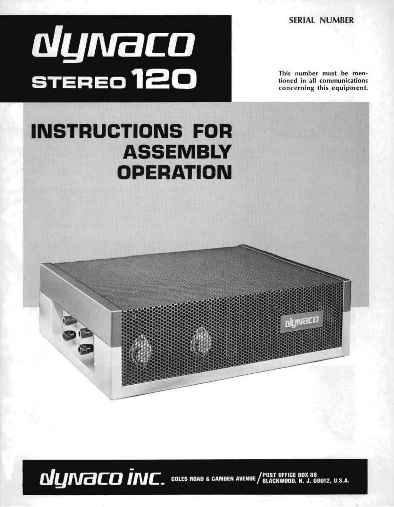
Dynaco ST 120 Service Manual

This is the 26 pages manual for Dynaco ST 120 Service Manual.
Read or download the pdf for free. If you want to contribute, please mail your pdfs to info@audioservicemanuals.com.

Page: 1 / 26
left right
Dynaco ST 120 Service Manual

Extracted text from Dynaco ST 120 Service Manual (Ocr-read)


Page 1

SERIAL NUMBER

NyNaca

This number must be men>

STEREO 120
concerning this equipment.

INSTRUCTIONS FOR
ASSEMBLY
OPERATION

POST umc: BOX 88
Numca INC. 5 0 8' MM" E""E/aucanno. N. J. 08012. U.S.A.

Page 2

ID

CONTENTS

Operating Instructions ...................... 3 Assembly Instructiom . . .................... 7
Technical lnlormatitin t . . r ................ 5 Schematic Diagram .. .. .................... 12
Grant Description ..................... 5 In Case of Difficulty ....................... 19
Perlormance Testing V . . , ............... 5 Sen/ice lnmrmation for the Technicran ......... 20
Dynaco Preamplifiers ................... 6 Factory Service and Warrantv ................. 22
4-Dimensiunal Sound Svslem v ......... fi Pictorial Diagram . . ......... Back Cover Foldoul
Rel Volt (-HUUIIIIITIIR 3 Parts lixt ........................... Back Cover
SPECIFICATIONS

FREQUENCY RESPONSE: 5 Hz to 100 kH7 :05 ill).

POWER OUTPUT RATING: ht) watts IWOFRgI, ('on-
Iinuous power pvr tliiiiiiiel min 8 Ohms at any
irequency between .45 H/ and l'i kHz til la» than
IL'IOJ'CI total liaii'mi'ilt tlistiiltinn. Distortion (ICI-
CFC-35135 at lower PUVI'Ef levels. lhis is. In ;I('([1F(l-
dHLE Witli FTC. rating t'tIIIIIH-ITHEHIS, INLlLlLllDR
tire-r(iiiililinmng,

INTERMODUIATION DISTORTION: LL25: than twain
(ll any [)(i\\il lit-vol up It: hll warn pt (imnrwl
into 8 ulmis mtli am, (tiriibiiiation cit IC'SI TI'IffttlLfT
(test [)Isliiiitiun rttlzitm .2! lower piiwCI' levii'h

3 00 H 3

lkHz

NOISE: 95 (lb below rated uulput umwjightml with
ulmrtetl input; IUO Cll'i down lay lHF \tantlards.

DAMPING FACTOR: Greater than 40 trom .20 Hz to
10 kt IL

SEPARATION: More than 3'0 rlh from 20 Hz to 20
kill.

INPUT: Inuiiuii (tiIlHN'I 1.5 volts in: ()0 watts output.
SEMICONDUCTOR COMPLEMENT:

1r) (litidLS
SIZE: i;'." \ who" x 4". WEIGHT: 2U lbs
MAXIMUM POWER CONSUMPTION: 400 wallk.

13 transixtnrs,

leHz

SQUARE WAVE PERFORMANCE: This is a good indication of linearity from
10 Hz to 100 kHz, SINCE good square wave reproduction requrres baridWidtli
in excess 0t li 10m to 10 times displayed frequency.

PkHz

INPUT~OUTPUT LINEARITY AT 60 WATTS

20 kHz

TONE BURST:

4 cycle 20 kHz through amprifier at 60
watts is indistinguishable from gener-
ator [below].

Page 20

with the Service information which follows, before proceed
ing. Unless you are confident that a local repair-nun has
the specialized knowledge and equipment for servicing high
quality solid state audio equipment. factory service is
strongly recommended.

SERVICE INFORMATION FOR THE TECHNICIAN
(FOR QUALIFIED PERSONNEL ONLY)

Before attempting to service the Stereo l20. be sure to
read the circuit description in the front of this manual. as
well as the preceding section, "In Case Of Difficulty".
Some of the amplifier's unique features are not immediately
apparent when examining this ementially simple circuit.
A systematic check of voltages and signal paths. based on
an understanding of the functioning of each section. will
lead to a rapid diagnosis of any malfunction.

Each of the four screws which secures the cover is lo-
cated between a rubber foot and the edge of the chassis.
All of the numbered test points are located along the edges
of each circuit board. Each of the three modules tpoWer
transistor heat sink and the associated circuit board) are
fastens! with only two screws. When them are removed,
the module may be tilted outwards to gain M30988 to the
wruponents.

Thoreare threcpnrtstothecircuit. Oneisthoregulatcd
power supply. The other two are essentially identical audio
amplifiers l but with changed physical layout). Capacitors
09. Cl], and cm provide power supply filtering and de-
coupling; and there is an output coupling capacitor C7 for
each channel.

There are mrtain genmnl precautions to be observed in
servicing any transistor-ind equipment:

1. Never make circuit changes (connections or disconnec-
tions) of any kind when the amplifier is turned on.

2. Bo particularly careful not to short any transistor loads
toeachotherortothechaasiswhen thepowerison.

3. When using test equipment. you must avoid h-snsient
voltage peaks and excessive test voltages.

4. Exercise caution when soldering and unsoldcring tran-
sistor and diode leads to avoid excessive heat.

Power supply

The power supply is designed to provide a constant 70
to 72 volts with demands up to 3 amperes and with power
line voltages between 110 and 130 VAC (between 220 and
260 VAC when connected for 240 volt use). Transistor Q9
is a series regulator using sen-(Hype action in which the
impedanceonSlisvarit-dastheloadchangcstoprovidea
constant output. This variation is accomplislwd by a nega-
tive feedback loop which compares the potentials at the
emitter and base of Q7. Differences furnish a corrective
signal which is amplified in Q8 and passed to Q9. Zener
diode Dill furnishes a reference potential at the emitter of
Q7. and a voltage divider at its base provides the compari-
son voltage. D10 is kept "alive by the current flow in R19.
However, when the current in Q7 exceeds the current in
319. 010 is starved". and its Zener action drops out.
Then. without a corrective signal, a regenerative action
causes the supply to cut off by increasing the impedance of
Q930thatltcarmotpasscurrent.

20

Amplifiers

There is a physical change of component positions for
the left and right audio channels, but they are electrically
identical. Each amplifier has two basic sections. The
direct-coupled pair Q1 and Q2 is the Class A amplifier-
driver with a DC feedback loop from the second emitter to
the input base. Audio signals at the input base of Q1 are
amplified and appear at the collector of Q2 to drive the
four-transistor Class 8 power output section.

Q3 and Q4 are a complementary-symmetry driver directly
coupled to Q5 and Q6 output power transistors. The Class
8 section provides a power gain, but no voltage gain. The
input junction of Q3 and Q4, and the output junction of
Q5 and Q6 swing together through the signal cycle. The
ability of the output junction to follow the input function
(and the consequent linearity of this section) depends on
the feedback path from the collector of Q6 to the emitter
of Q4. Variations at Q4 emitter compared to its base poterr
tial will create a corrective signal for Q6. which makes the
output follow the input.

Diodes D2 and D3 are in this feedback path. in a direc-
tion which would not be conductive (breaking the feedback
path) were it not for the forced current through bleeder
"austere RIG and R17. When the current in Q4 reaches
that in RlGand Rl7. IhediodcsD2and DSnolongercrm-
duct. and the feedback path is broken. Simultaneously DI
starts conducting and makes a short circuit between the
input of Q3 and Q4. and the output of Q5 and Q6.

Thus when the current demand in the feedback loop
exceeds the limit determined by the bleader ralstora. the
ability of the circuit to drive is restricted. and excessive
wrrents cannot be induced in Q5 and Q6. The action of
Dl short circuits the drive from Q2, reducing the drive
until the (reuse of the high current demand is corrected
'I'hus an excessive drive signal, or too heavy a load on the
output. which would require excessive current. switches the
circuit to a configuration which prevents damaging current
flow through the output and driver transistors.

Trouble shooting the power supply

When the supply is performing properly. its voltage in a
given amplifier remains within 1% of its nominal value
over the operating range, and should be within 5% of the
specified 72 volts. If the output is 80 volts or more. Q9 is
probably shorted. Tests for gross transistor defects are
described in a later section. An output of less than 65 volts
indicates that the supply is either deficient or being over-
loaded. Turn off the amplifier and detach the wires to each
of the amplifier modules at the positive terminal (8) of
C12 so that the amplifier sections will be separated from
the power supply. It normal supply voltage is obtained
with tlu-se wires detached. then connect one amplifier lead

atatimetoseeifonechannelisloadingthempply
excessively.

Verifying the supplys performance under full load and
under heavy load. as well as checking the 72 volt output.
is necessary to assure normal supply operation. A suitable
full load test can be made by connecting a 200 watt. 25 ohm
resistor across the supply. This provides about 2.8 amperes
current drain. The voltage output of the supply should not
vary more than :1 volt. With a heavy load of 5 ohms.
or even a short circuit. the current delivered should not
exceed 0.5 ampere.