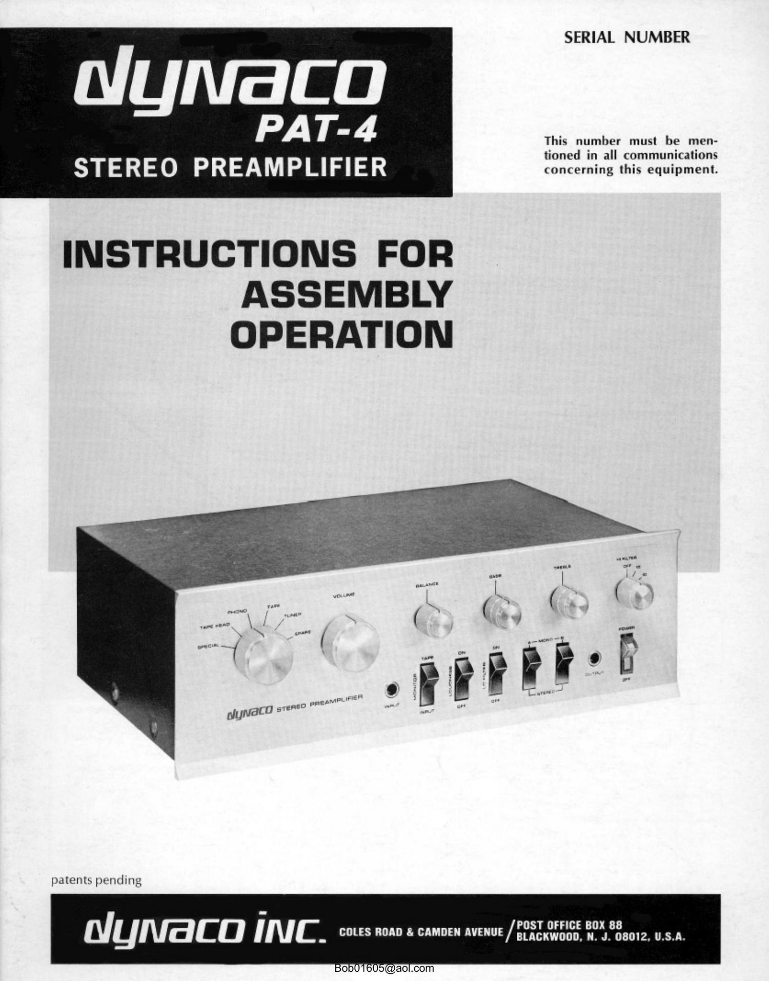
Dynaco PAT 4 Service Manual

This is the 26 pages manual for Dynaco PAT 4 Service Manual.
Read or download the pdf for free. If you want to contribute, please mail your pdfs to info@audioservicemanuals.com.

Page: 1 / 26
left right
Dynaco PAT 4 Service Manual

Extracted text from Dynaco PAT 4 Service Manual (Ocr-read)


Page 1

SERIAL NUMBER

nlymaca

PA14-4
This number musl be men-

tioned in all communications

STERE O PREAM PLIFI ER concerning this equipment.

INSTRUCTIONS FOR
ASSEMBLY
OPERATION

patents pending

posr urnc: BOX 88
OIL-ECU I N C - col "0 8' MM" VNUE/Bucxwoon. n. J. 08012. U.S.A.

Page 2

Operating Instructions ............. . . . . . . .
Technical Information
Circuit Description . .
4-Dimensional Sound System ..........
Optional Connections ... . . . . . . ..
240 Volt Connections .. . . .. .

Frequemy Response:
Distortion at rated

2 volt output:

Hum and Noise:
Cain:

Tone Control Range:

Maximum Output:

Impedances:

Inputs:

Outputs:

Controls:

Semiconductor Complement:


CONTENTS

\IVOOGW

Parts List

SPECIFICATIONS

High Level inputs: :03 (lb from 10 Hz to IOO KHz
Low Level inputs- " 1 db irnm Jtl H7 in 20KH7 (equalized)

THD less than 0.05"? 20 Hz to 20 Kl lz
IM less than (103; with any eornbindtinn of test lrtlalltltt'lts

70 (lb below :t 10 mv iant signal
H5 (lh below a 05 volt input Signal

Magnetic Phono-
lligh Level-

54 db at moo ll!
Roda

Magnetic Phono:
High level:

i1hdh® 50 Hz
+12 dh @ 10 KHz

10 volts into high impedance
5 volts into 6m ohms

Magnetic Phone: 41000 ohms

Tape Head: 100,000 ohms
High level: '100,C00 ohms
AudioOutput' 600 ohms
To Tape: lrom low level inputs, ()0) ohms

from high level inputs. same as source
Amplifier Input: \ominal load 10,0Ll0 ohms or higher

low level or high level RIAA magnetic phono or cemmic phono. NAB
Tl) tape head: Special (normally microphone]: Tape amplifier,-
luner; Snare high level tor TV. etc, Front panel high level

Tape output ahead of rontrols. 2 Audio outputs lone switLlIed by
front panel jaclti; lrunt panel output

Selector switch, Volume control: Balance control; 2 Bass controls;
2 Treble controls; High Filter switch 1ng l5 Kill, 10 Km and It KHI,
Loudness compensation switch; Tape Monitor smith; luw filter
switch; paired Stereo-Mono switches to provide A or B channels inde-
pendently or combined [A I [ll With 6 (lb hlend ior 3rd channel output
or stereo; illuminated power sWItch

fl transistors; 2 diodes


Dimensions: 13%" Wide by 65/4" high by 9" deep
Shipping Weight: 10 lbs
Power Consumption: 5 watts
um » ,.. , l .3.
livid-inn» (rm-ilwtxlimltlif j
H
I: db r.
l l
l n 1"
.r. . l .. WNW iii/l .. Ah
Vallu 'IlhVi l l
l
em , .n age - h:-
l t i
All i lll..lll 1'l 1.1. Al..l. t
3- <4:- 1titi It: lllllll SLI'JJ 32134:: lit Wit "It; fit Illlrll 'rui .Iiititu

FILTER ACTION

TONE CONTROl RANGE

Bob01605@aol.com

tll

Assembly Instructions . . . . . . . . .
Schematic Diagram ............
Voltage Chart ...... . ....... .
In Case of Difficulty ..........
Factory Service and Warranty .

100 Hz Square Wax-e

'lll KH7 Square Wave

2 rvrle it'll) H7 Tone Burst

rvcle 10 Kill Tone Burst

Tunl' lmriI; are inrlistinguwhahle at out-

put of

PAT-4 ultupi from generator out»

put iiiottoml

l |


I: I)

4+

llil
ll

r m

i i

1mm twirl rm ~spt»-ir.al\
i

l

l

l
l

s -tl.ll

RIM Plum:

l r
At LLl Ill
1! lllllil
EQUALIZATION

Page 5

The normal or flat position is centered, with increasing
effect to the right, and a decrease to the left. Tone con-
trols alter the original signal to suit the user; but these
alterations are deviations from truly accurate reproduction.
The reference point should always be the center, which
gives no frequency discrimination. The tone controls also
help to correct for record compensation characteristics of
older discs which do not follow the present RIAA standard
playback curve.

The special tone control design in the PAT-4 is a
patentcd Dynaco design which assures that the tone con-
trols are out of the circuit when they are centered. This
provides the convenience of continuously variable correc-
tion without the complimtion of extra disabling switches.

High Frequency Filter

The Hi Filter rotary switch gives sharp reduction of the
frequencies above the points which are marked (in KHz)
on the front panel. The first step away from flat" is
barely detectable, being at the extreme of the audio range.
Further steps have an increasing but still subtle effect.
The 15 KHz position may be useful in filtering out super-
sonic disturbancos when recording from some stereo radio
programs. Successive steps will assist in reducing high
frequency distortion in poorer program sources.

Monitor Switch

The Monitor switch enables direct comparison of the
source signal as indicated by the selector switch, with the
same signal played back from the playback amplifier of a
tape recorder. This feature is applicable when recording
through the PAT-4 to a tape recorder which has separate
preamps and 3 or more heads designed for simultaneous
playback while recording. For example, while recording
from a radio tuner, the selector switch is on Tuner, and
To Tape is connected to the recorder input. The play-
back output of the recorder is connected to Tape Amp."
You will hear the tuner directly when this switch is in the
normal Input position. When it is switched to Tape, you
will hear the program played back from the tape a fraction
of a second after you have recorded it.

Loudness Switch

The Loudness switch is normally left "Off, but it may
be used at lower settings of the volume control to provide
an increase in bass to compensate for the car's lack of
sensitivity to low frequencies at low sound levels. The
high fidelity purist usually avoids any such compensation;
but many listeners will find this switch, used in modera-
tion, adds listening enjoyment at low levels. This sonic
correction does not add boom or muddiness to the
reproduction.

low Filter Switch

When 0n the Low Filter reduces the level of signals
below 100 Hz, and thus minimizes rumble and similar low
frequency disturbances.

Stereo-Mono Mode Switches

The pair of switches marked Stereo-Mono is normally
left in the stereo position, with the bottom of each switch
depressed. They provide three additional choices: I) The
left input channel "A is switched through both outputs by

depressing the top of the A" switch alone; 2) conversely,
the right input channel B is available at both outputs
when "B" top is depressed, and the bottom of "A is de-
pressed; 3) a partially blended mono signal is obtained at
both outputs by depressing the tops of both switches.

Whenthetopsofbothswitchesaredepressedthisisa
blendedpositiontobeusedforcombinedchannelmono
signals. 'IhisgivesGdbofseparationandisdesirablefor
reducing the apparent separation between stereo speakers,
or for establishing the proper spatial effect for more
natural sound in stereo headphones. This is the normal
position for playing mono records with a stereo cartridge.
This position is aha used with the Dynaoo 4-dimensional
sound system, and four speakers. This 4-dimensional sys-
tem is described in the Technical Section of this manual.
The Technical Section also describes the minor wiring
change to obtain a fully blended (A+B) mono signal if
desired.

Since the stereo-mono switching system enables you to
play a mono program through both output channels, it is
possible to have extra mono inputs by using the Spare or
Special positions for different signal sources in the left and
right inputs. For example, a TV input could be selected
for the Spare A input, and a mono tape machine for the
Spare B input. Then selection between these would be
made with the stereo-mono switches.

Front Panel Input"

The front panel Input jack will override the selector
switch and cut out the signal from all other inputs when
a phone plug is inserted. This is a normal high level input,
identical to the Tuner and Spare inputs. You may wish
to connect a tape recorder here, but remember that the
Monitor function is not operable on this input. Another
possibility is to insert the output plug from a musical
instrument requiring amplification, such as an electronic
guitar. If the plug from a mono source is only partially
inserted (to the first detent, or notch) then only the right
channel is activated by the front panel input, and you can
mix a guitar, for example, on the right channel, with a
record (selector switch on phone) heard on the left chan-
nel. You can adjust relative levels with the balance con-
trol. If desired, you can mix the two signals (if they are
already properly balanced) by depressing the tops of both
mode switches. Thus you can accompany a musical instru-
ment with a record, tape, radio, or a microphme.

If a mono phone plug is fully inserted, it will provide
signal to the left A channel only; then depressing the
top A" button will switch it through both output channels.

Front Panel "Output

The front panel Output jack provides a normal 600 ohm
output in parallel with amplifier Output 1 on the back
panel. Connecting to the front panel output mutes Out-
put 2 on the rear, enabling the use of headphones, for
example, to automatically cut out the speakers.

If an amplifier is connected to Output 1, which is not
muted by the front panel jack, the introduction of head-
phones will cut the amplifier signal approximately in half.

Headphones should be of medium impedance (nominally
600 ohms) or higher. If only low impedance (4 to 16
ohms) headphones are available, such as are normally con-
nected to amplifier outputs, then a matching transformer
should be used.

Bob01605@ao|.com 5