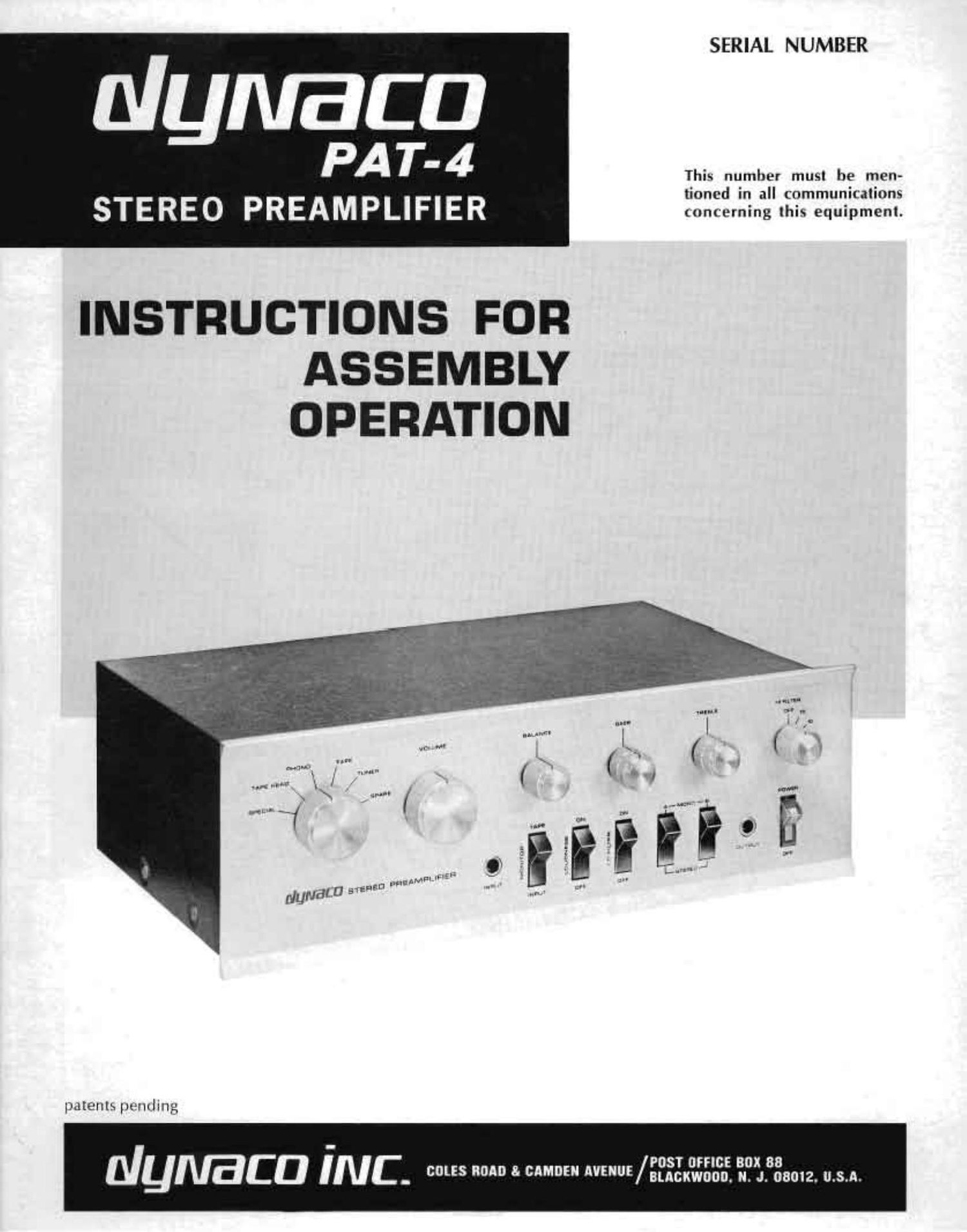
Dynaco PAT 4 Owners Manual

This is the 26 pages manual for Dynaco PAT 4 Owners Manual.
Read or download the pdf for free. If you want to contribute, please mail your pdfs to info@audioservicemanuals.com.

Page: 1 / 26
left right
Dynaco PAT 4 Owners Manual

Extracted text from Dynaco PAT 4 Owners Manual (Ocr-read)


Page 1

SERIAL NUMBER

Nymaca

PA14-4 .
This number musl be men-

tioncd in all communicatinne

STEREO PREAMPLIFIER concerning this equipment;

INSTRUCTIONS FOR
ASSEMBLY
OPERATION

patents pending

POST nmcs BOX 88
NyIVBCD INC. was 0 "0 5" BLAcKwoon. N. J. 08012. u.s.n.

Page 2

Optional Connections
240 Volt Connections

Operating Instructions ... . .. .. . . . . . . . . . . .. 3 Assembly Instructions ... .
Technical Information ................ . . .. 6 Schematic Diagram .....
Circuit Description ... . . . ... ...... ... 6 Voltage Chart .. . . . . . . . ..
4-Dimensional Sound System ...... . . .. 6 In Case of Difficulty ......

7

7

Frequency Response:
Distortion at rated

'1 volt output:

Hunt and Noise:
Cain:

Tone Control Range:

Maximum Output:

lmpedantes:

Inputs:

Outputs:

Controls:

Semiconductor Cumplcmenl:
Dimensions:
Shipping Weight:

Power Consumption:

.ii'i


. t
t l
7 -Lu him;

i 'l
(Ilfllr'xu (tiniIq-ihdlltm

I Hilllll
"fie,

CONTENTS

SPECIFICATIONS

High Level inputs' :05 (lb tmm 10 Hz to 100 KHz
Low Level inputs: " 1 db from 1 H! m ID KH7 (equalized)

THD less than (1.05% 20 Hz to 20 Kt l1
lM less than 0.03"; With any Combination ol lest lrtlllltllt new

Magnetic Pliomi- 70 db below a 10 mv input signal
High Level' 85 (lb below a 115 volt input signal

Magnetic Phono: 34 db at "m I
High level, 20 do

:11) db @ 50 Hz
+12 db @ 1i) Km

to volts into high impedance
5 volts into 600 ohms

Magnetic Phono' 470(1) ulii'is

Tape Head: 100.000 ohms
High level: l00,C00 ohms
Audio Output 600 ohms
To Taper linm low level inputs, 600 ohms

from high level inputs, same as source
Amplifier Inpul Nominal load lUtlUtmiiiiis U! higher

low level or high level RlAA magnetic phonu or ceramic phono; NAB
75.4" l.tpt' head. Special (normally Inicrophonrz'lg Taupe amplifies!r
tuner; Span? high level tor TV, etc., Front panel high level

Tape output ahead of rontiols; 2 Audio outputs lone switi;lied ll)
front panel iacki; lruit uanel output

Selectoi switch, Volume control: Balance control: 2 Bass controls:
2 treble (ontrols; High Filter sthch (gt 15 Kill. 10 KHz and 2' KHz,
LOUllIIBSS compensntion switch: Tape Monitor 5Wlltll; Luw Filter
switch: paired Stereo-Mono switcher. to provide A or B channels lode.
pendently or combined [A l Iii Willi 6 (lb lilenrl for 3rd channel output.
or stereo, illuminated power swrtth

it transistors: 2 diodes
UV-i" Wide by 4%" high by 9" deep
10 lbs.

5 watts


i'l lll _'

. m

PM?
it ' |

II I!


ll ll l. lli

it i litili

um It: ttlliii

"HER ACTION

mun ZEAZU. an in mi: m Him 7- - ,vmuu

TONE CONTROl RANGE

Factory Service and Warranty
Parts List

illil l\

....... 12
14
21

ICCI Hz Squtiie Wave

10 KH7 Square Wave

2 cycle 100 Hz Tone Burst

1 twle it] it'll; lnne Burst

lovw hunt; at? IQFlISlIrtgtllNlflllllt" at out»
put u." PAT~8 tiuoi iiozn generator out-
put tbuttoitii

.i.

gt L
i )L

H-Mn iilv;ilii iiw "\fl§l':lfll\

i? iii

no «1 mail

ii
A imam
l

EQUAUZATION

Page 7

efficiencies and locations. A switch to disconnect the back
speaker is advisable for listening to noisy programs.

Since the speaker impedance isolates the amplifier ter-
minals. no amplifier damage results from this connection
from hot" to hot. No back speaker connection is made
to a ground terminal, If the amplifier design cautions
against connecting its ground terminals together. which is
mre, then the front speaker should be eliminated, and the
left and right speakers connected normally.

To balance the system for 4~D playback, disconnect the
ground return from the front. switch the PATA to A" only.
and play a record with the volume control at its most-used
setting. Adjust thr- bolance control for minimum output
from the speakers. Then adjust the tone controlsapret'cr-
ably to the flat settings? for rm'nimum output. The tone
controls need not be flaL but will null when the two chan-
nels are identical. You can reposition the knobs on their
shafts to indicate the center null position. Reconnect the
center ground. and switch the preamp to the A+B l6 db
blend) position i depress the tops of both switches). This
is now the normal stereo playback mode when using 4
speakers. The blending is equal in amplitude and opposite
in polarity to the crest-ilk introduced by the center (front)
speaker connection, which cancels the crosstalk and insures
full m-[mration at the. speakers.

The same connection for the. front speaker, which repro-
duces a combined mono signal. enables it to be used as a
remote speaker as an alternative. or as a center~fill when
the side speakers are unusually far apart.

OPTIONAL CONNECTIONS

The design of the PAT-4 makes it easy to customirc
in several ways to suit individual needs. A few of these
are described here.

A+B Full Blending

If you wish the to provide complete blending with the tops of both switches
depressed. rather than the normal 6 db separation, connect
a short piece of wire across the. 7.500 ohm (violet-green-
redJ resistor between lugs #2 and #5 of switch AS. You
need not rcmova the resistor.

Special Phono Input

If, instead of a microphone input, you wish to use the
Special position for a second low level phonograph input
with RIAA equalization (so that you might uw a separate
changer and turntable. for example; change each channel
for stereo as follows: Remove the wire from eyelet #8 on
the circuit board. Do not disconnect the other end from
rein lug #2 of the selector switch wafer, but shorten the
wire and solder the free end to lug #4 of the same water.

Provision for Other Equalization

There is a separate group of equalization components
for each low level input on each circuit board. Other
values can be substituted to provide special variations if
desired. R7, R8. (15 and (36 are in the Phono channel.
R10. fill and CB aflcct the Tape Head input. R9 and C7,
together with the wire jumper on the board at that point,
control the Special input as used for microphone.

It is necessary to connect to separate input sockets,
rather than simply bridging from one position to the next,
when changing from one equalization position to another,
because of the automatic shorting of the unselected low
level inputs incorporated in the selector switch to elim-
inate feedthrough from unused inputs. Such shorting
action can be removed only by deforming the selector
switch contacts on the back of each switch wafer.

Driving a Third Channel Amplifier

A simple arrangement to power a center channel speaker
without the need for an additional amplifier has been
given earlier. This is an alternate approach to a three
channel system.

You can obtain a combined channel signal to drive a
third channel separate amplifier by connecting one pair of
outputs together through isolating resistors, and taking the
signal from their junction. For example, a 47.000 ohm
t-{g watt resistor in series with each output will maintain
adequate separation between the main channels, provide
a medium impedance output, and will be only about 6 db
lower in signal level than the main channels. A 100,000
ohm or higher value potentiometer could be used as a
center channel level control from this junction.

CONNECTIONS FOR 240 VOLT AC LINE

The power transformer supplied in the PATH may be
connected for a 240 volt AC line as well as for the stan-
dard 120 volt AC line. which is how the transformer is

.connech-d unless this manual is stamped "240 volt." The

transformer has dual primary windings. They are con-
nected in parallel for 120 volts, and in series for 240 volts.
The noun; to Steps 37. 40 and 41 on page 18 and the dia-
gram on page 23 detail the 240 volt connections.

The 1/10 ampere (100 mu) slo-blo fuse supplied with
120 volt wiring should be replaced with a 1/16 ampere
<62 ma) sIo-blo fuse when the preamplifier is wired for
240 volt use.

The. PAT-4 is designed for use. with either 50 Hz or 60
Hz current. Variations of line voltage up to 10% from
nominal value will not attect performance.

ASSEMBLY INSTRUCTIONS

GENERAL ASSEMBLY INFORMATION

Assembly of the PAT-4 is exceptionally simple when
compared to other kits. The preassembled etched circuit
boards have saved you much of the work, and the. assembly
that remains is arranged in an open. uncluttered layout
that makes wiring quick and easy. The construction time
will be several hours. It is better to work slowly and care-
fully rather than worry about the time.

When you unpack your kit. check off the components
against the parts list at the back of the manual. You can

identify unfamiliar parts by matching them to the pictorial
diagram or photograph.

Have the proper tools at hand before starting assembly.
You will need a pencil-type soldering iron of 30. to 60mm
rating with a small tip. long nosed pliers, diagonal cutting
pliers, a medium-sized screwdriver, and 60/40 rosin core
solder not larger than l/m" diameter. You will also find a
damp sponge or cloth helpful to wipe the tip of the iron
clean periodically. An inexpensive wire stripping tool is
helpful, but some people prefer a single-edged razor blade
for removing the insulation.

Page 25

SPARE

TUNER

TAPE AMP

TAPE H EAD

SPECIAL

PHoNo HIGH

PHONO C ER

PHONO LOW

SELECYOR SWITC
CLOCKWISE POSIT
SHOWNV
FRONT SIDE

15 BLACK DOT REAR SIDE
I INDICATES VIEWED FROM
FRONT SIDE

3 |

2 |

I
| .256 " .ozml

335201 -.-.I:'- _ I

NOTE -


B, IO, AND

RESPECYI
0N TN! F
OF THE S

| FEEDTHRU


LUG 5 NO. 5,7,

MECHANICALLY CON~
NECTED To THEIR

9
e

|| ARE

HIS

SHOWN IN THE COUNTER-

ION.

REAR WAFER (LEFT CHI)

AA
v
z:
u

OI 5

vvv
m
n

VE LUGS

RONY SIDE
WITCH.

INPUT JACK

MONITOR

Lo FILTER

+
ALL-THE
-o
CIIO+
I
LUG 9 LUG l2
FRONT WAFER OF
SELECTOR SWITCH
(RIGHT CH)
POWER
I20 Vans 3] BLACK
cha
RED T ? VIOLET
WHITE
F I
x sLAng
- r_-| :3 W E
~VIOLET

RI2

Tl

03 ms

TREBLE

+0 9
To TAPE
OUTPUT l
OUTPUT 2
R 27 ='

|
I
as
R 2| I
w. 4(9) I
I0 I
NOTE_ HI FILTER IS SHOWN IN THE
I ALL WIRING NOT SHOWN FOR THE c COUNTER CLOCKW'SE 0"
I RIGHT CHANNEL Is THE SAME As THE OFF POSITION,
LEFT CHANNEL, WHICH Is SHOWN.
I RESISTOR AND CAPACITOR NUMEERS
ARE THE SAME FOR THE PARTS 0N OUTPUT JACK
P C - I 6 I BOTH CHANNELS. FRONT WAFER LUG z
REAR
----_---._| {hR WAFER >-:g:--V
Q I 4: 2,, L 7!
c c 26 0 (23 A
I. .. . ,. "I a
A STEREO a c 24 ® .7 . G c 23
9 c 25
I- OUTPUT 2
c 22 RIGHT CH,
\-
LOUDNESS R 25
-1 THUG = :IJIIII
? - R 26 In?"
4 I BALANCE LUG |O-W-
.. I :.
7 F
ww->
R ,3 MONO ic I2 1-5,: I LUG 4
.'.'.' I
Rm Rm
0 o I e |
_ __ I 4: L. EYELET
' ' Is RIGHT
I CH
1
c
v m
_I-
= 9 IO 4:24 ., 9 0
EYELETS 0N L71 3 .
PC Is FOR __
RIGHT CH. we a r
FRONT WAFER REAR WAFER
POWER
,, SCHEMATIC
A B '
m DIAGRAM
RED VIOLET
+ A + 3 + 0 WHITE
c 29 C29 I229 it,
02 BLACK
c _ I: WHITE 13
VIOLET