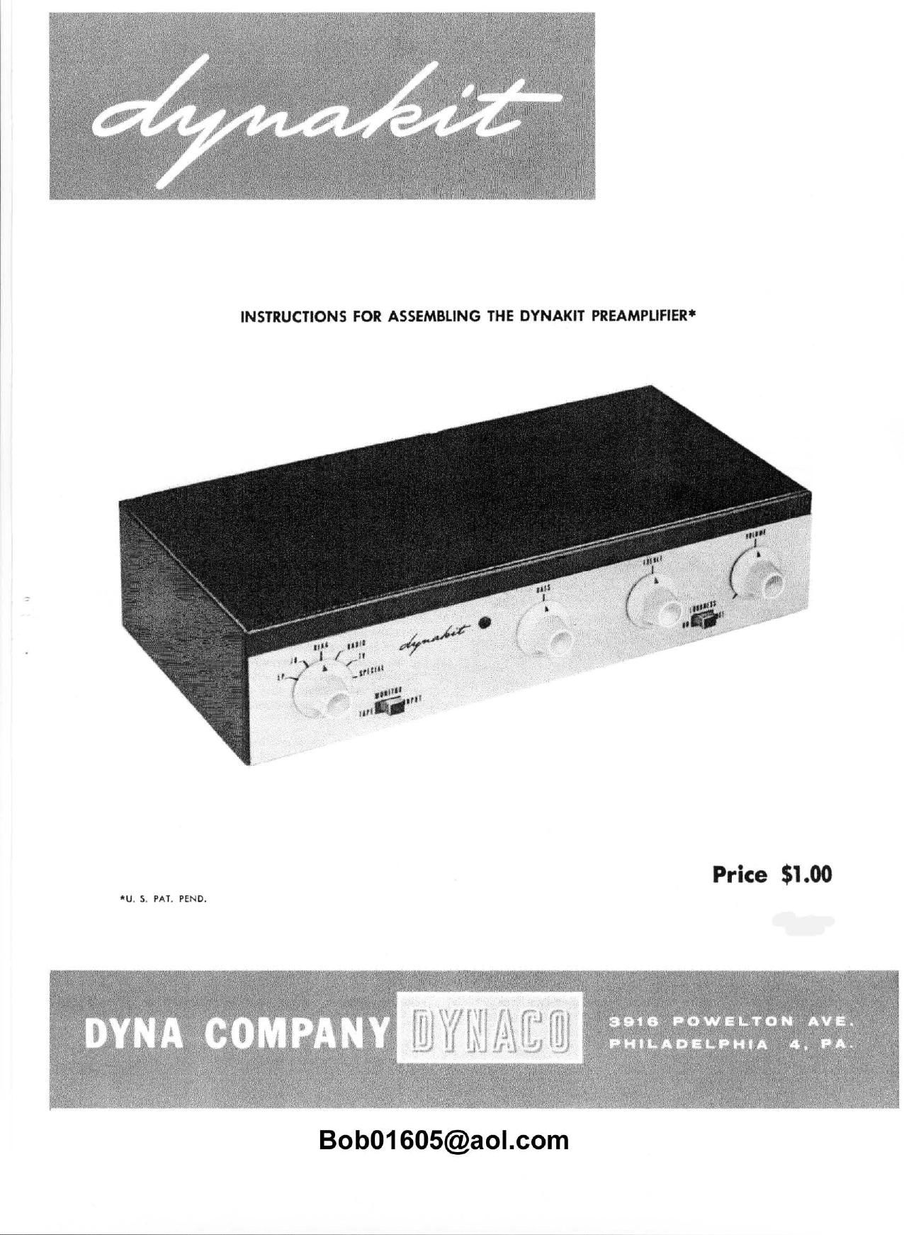
Dynaco PAM 1 Owners Manual

This is the 17 pages manual for Dynaco PAM 1 Owners Manual.
Read or download the pdf for free. If you want to contribute, please mail your pdfs to info@audioservicemanuals.com.

Page: 1 / 17
left right
Dynaco PAM 1 Owners Manual

Extracted text from Dynaco PAM 1 Owners Manual (Ocr-read)


Page 1

INSTRUCTIONS FOR ASSEMBLING THE DYNAKIT PREAMPLIFIER

Price $1.00

U S. PA'I, PEND.

Bob01605@ao|.com

Page 2

INSTRUCTIONS FOR ASSEMBLING THE DYNAKIT PREAMPLIFIER

DESCRIPTION

Your Dynakit preamplifier is a versatile preampli-
fier control unit which permits using any modern pro-
gram source with your Dynakit or other power ampli-
fier. This preamplifier uses a new circuit (patent pend-
ing) in which both voltage and current feedback loops
include every tube section. These feedback loops give
tremendous stability and consistency of performance,
greatly reduced distortion, and exceptionally low noise.

The Dynakit preamplifier contains an unusual design
arrangement. A single 12AX7 tube acting as a feedback
pair with equalization determined by feedback at fre-
quency extremes acts as a low level amplifier for
magnetic cartridges. microphone, or tape head. This
section has a voltage gain of 50 to bring up low level
sources to a point comparable to inputs from high level
sources such as radio tuners. tape recorders. etc. A
second 12AX7. acting as a similar feedback pair. is the
tone control section; and tone control action is adjusted
by control of feedback at frequency extremes. This
section has a voltage gain of 10 bringing the various
inputs up to a high enough level to energze any popular
power amplifier.

A volume control and switching system interconnects
these two feedback pairs. By this type of arrangement,
signals are attenuated before going into the tone control
section so that there is no possibility of overloading
regardless of the amplitude of the signal source. There-
fore. distortion is unaffected by the position of the
volume control. In many preamplifiers distortion islow-
est with the volume wide open but rises significantly
with the volume in the normal listening positions. This
is not true with the Dynakit preamplifier.

The circuit arrangement used also eliminates fre-
quency discrimination for different positions of the vol-
ume control. in much equipment on the market the high
frequency response is lost when volume is reduced. This
is not true in the Dynakit preamplifier where nothing is
changed except the total gain by varying the volume
control.

The Dynakit preamplifier is intended as a complete
control unit so that there is no need to have the power
amplifier in a convenient location. All switching of the
audio circuits as well as control of the ac power to the
auxiliary equipment is controlled from the preamplifier.
A bullt in rectifier supply which converts the filament
current to do permits extremely quiet operation regard-
less of the power source to which the preamplifier is
connected. These features make the Dynakit preamplifier
completely independent of the type of circuitry from which
it is powered.

GENERAL WIRING PRACTICE

Assembly of the Dynakit preamplifier is quite simple
compared to general kit assembly requirements. This is
true because all critical parts of the Dynakit are factory
assembled for you on the printed circuit assembly. Other
parts are put out in the open through a free and un-
cluttered layout so there is easy accessibility for wiring
or trouble shooting purposes. Construction ofyour Dyna-
kit should not take more than about six hours because
of these simplifications.

Tools required for easy assembly of your Dynakitare
soldering iron (small tip) or soldering gun. long nose
pliers. screwdriver, and wire cutters. Although not es-
sential. a low cost wire stripper and cutter of the type
which can be purchased for less than $1.00 will greatly
facilitate cutting and stripping the various leads in the
kit.

Good soldering technique is valuable in obtaining
satisfactory results from any electronic equipment.ALL
SOLDERING MUST BE DONE WITH ROSlN CORE SOL-
DER. There is no warranty on any equipment in which
acid core solder has been used. Make sure that the solder
used is plainly marked Rosin Core. Wheneversolder-
ing is required. the assembly instructions specify it by
"(5). If this symbol is not shown after a connection is
specified. it indicates that further connections will be
made at that point before soldering.

Soldering is accomplished by heating the joint with
the iron until solder is hot enough to flow when touched
to the joint. It is not desirable to feed the solder to the
iron. It should be fed to the junction of iron and joint.
After the solder flows,the iron shouldbe held in place for
a few seconds and removedwhen itis seen that the solder
has contacted both parts of the connection - the lug and
the wire to which itis connected. ltshould not show a ball
of solder but a smooth transition from solder to compon-
ent lead.

Before applying solder the joint should be clean and
the lead should be crimped in place so as to have mech-
anical security. it is not necessary to wrap leads around
contacts many times. A single turn and pinching together
with long nose pliers is suitable. After soldering. there
should be no play at the joint if the lead is wiggled with a
pair of pliers. It is practical to do all soldering with a
pencil type iron of low wattage rating. A small tip is
extremely useful when working in :1 confined space. If a
soldering gun is used. it should be used with discretion
since the amount of heat available is far more than
required for soldering light wires.

Bob01605@ao|.com

Page 7

(>24.

()25

()26

()27

()28.

()29.

()31

()32

()33.

()34.

The terminations on the two phone inputs will
handle practically all cartridges. However, ii a
lower impedance is desired. it can beobtainedby
adding resistance directly across the cartridge
terminals. For example. 56.000 ohm resistor a-
cross the cartridge will make the total load on
the cartridge about 27,000 ohms whichis the sug-
gested termination for older models of Pickering
cartridges. If s 100.000 ohm termination is re-
quired for low level phonoinput,it cnnbe obtained
by changing the 56 .000 ohm resistor on the printed
circuit board to 120,000 ohms.

Connect a 3-1/4" wire from input socketitz (S) to
rear deck lug #5 (S) on switch.

Connect 3-1/4" wire from input socket #1 (S) to
rear deck lug #2 (S) on switch.

Connect 2-1/2" wire from rear deck lug #10 to
eyelet #3 (S) on printed circuit board.

Connect 2-1/4" wire from rear deck lug #11 (S)
to eyelet #2 (S).

Connect 3-1/4" wire from ground junction of in-
put sockets #1 and #2 (S) to rear deck lug #10 (S)
on switch.

Connect hanging wire from forward switch deck
lug (ti to eyelet #1 (S).

. Connect .05 capacitor from #4 lug on volume con-

trol to #3 lug on loudness switch. This capacitor
goes under the control close to the chassis. The
leads should be kept clear of the wires which go
to the switch on the rear of the volume control.

Connect 2-1/2" wire from #4 lug on volume con-
trol (S) to #2 lug on loudness switch (S).

Connect 10.000 ohm (brown-black-orange) resis-
tor from its lug on loudness switch (S) to #3 lug
on volume control. Swing body of resistor over
control so no part of the leads touch the control.
Use sleevlng on the bare leads if necessary.

Cut lead on 470.000 ohm (yellow-purple-yellow)
resistor until it is about 3/8" long, and bend a
hook in this end. Do the same with 100 mmid
capacitor. Crimp the two hooks together and sol-
der so that the capacitor and resistor are joined
together with only a short lead between them.
Connect the free lead of this capacitor to #1
lug on the loudness switch (S). Connect the free
end oi the resistor to lug #1 on the volume con-
trol (S).

Take two 8" wires, fasten one to eyelet #8 (S)
on the printed circuit board and the other to eye-
let #9 (S) on the printed circuit board. Kink the

()35.

()36.

()37.
()38.

()39.

()40.

()41.

()42.

end of the one which fastens to eyelet *9 so as to
identify it after twisting. Twisttogether and carry
across the top of the chassis (where it will lie
against the cover when the cover is closed). The
wire with the kink goes to volume control lug #3
(S) and the other wire goes to lug #2 (S) on this
control.

Take thc 4 conductor cable. Strip the outerjacket
back two inches and strip the end of each lead
back about 1/4". insert rubber grommets in the
two holes adjacent to the hum balance control
(below the ac receptacles). Insert the stripped end
of the cable from outside the chassis through the
#1 grommet hole until it is inside chassis. Tie
a figure 8 knot in the cable about two inches bc-
hind the stripped section and pull cable back until
the knot pulls tight against the back panel.

Connect the black wire to capacitor mounting
prong to which wire from lug terminal #3 was
previously connected (S).

Connect the red wire to capacitor lug #3 (3).
Connect the white wire to lug terminal #7 (S).

Connect the green wire to side lug (yellow dot) of
selenium rectifier (S).

Slide the cap over the free end of the cable, Strip
the outer jacket of the cable hack 1-3/4". Strip
each wire about 3/4". Each ofthe wires should be
tinned by heating it with a soldering iron and
applying a very thin coat of solder. Thiswill make
it easier to solder these wires when they are in-
serted in the pins of the plug. It is easier to
solder to the pins of the plug if the tip of each
pin is reamed lightly by inserting the point of a
knife or tile and rotating it so as to scrape the
plating on the pin.

Insert the white wire into the #1 pin on the octal
plug. Insert the green wire in the #2 pin, the
black wire in the #3. the red in the #5. until the
ends of all these wires protrude. Hold the sol-
dering iron against the tip of each prong in turn
and feed solder to the hole where the wire pro-
trudes until the solder runs freely into the hole.
Do not get solder on the sidesof the prong or you
will have to file it off inorder for the prong to be
able to plug into the socket. After soldering. trim
excess length of wires which protrudcmsingwire
cutters.

Strip 2-1/2" of wire and bend it in a close U.
insert this through pins its and (VI on the octal
plug. thus making a link between these. Solder
these wires as was done with the wires in the
cable. and trim off the excess wire. Then snap
the cap on to the socket.

Bob01605@ao|.com