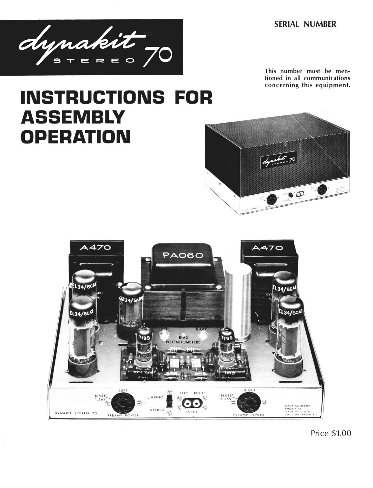
Dynaco Dynakit ST 70 Owners Manual

This is the 18 pages manual for Dynaco Dynakit ST 70 Owners Manual.
Read or download the pdf for free. If you want to contribute, please mail your pdfs to info@audioservicemanuals.com.

Page: 1 / 18
left right
Dynaco Dynakit ST 70 Owners Manual

Extracted text from Dynaco Dynakit ST 70 Owners Manual (Ocr-read)


Page 1

SERIAL NUMBER
I

STEEEOO

INSTRUCTIONS FOR

This number must be men-
tioned in all communications
concerning this equipment.

ASSEMBLY
OPERATION

FOWNTIOMEYER

' A ;M-.»
. MU! V -
ausev M am
\ 56v F r m»_
if " " ' 7
zvraso 7 "NV, 1:,
LDVNAKIV svsnro 70 MW, HM \ . ynnmw row . 4v uvsn I

Price $1.00

Page 2

Power Output

Frequency Response

Power Response
Intermodulation Distortion
Hum and Noise

Sensitivity

Output Impedances

Damping Factor

Minimum Channel Separation
Power Consumption

Preamp Provision

Tube Complement
Size
Weight

Finish

SP ECIFICATIONS

35 watts continuous, 80 watts peak each channel

t .5 db from 10 cps to 40 kc

20 cps to 20 kc within 1 db of 35 watts at less than 1% distortion

Less than 1% at 35 watts (normally about .570). Less than .05% at 1 watt
Inaudible; better than 90 db below rated power

1.3 volts rms input for 35 watts out

4, 8, 16 ohms each channel

15

55 db

190 watts 50/60 cps

Two power takeoffs with independent heater windings to eliminate
interaction. Each 6.3 volts 1 amp, 350 volts do 10 ma. Dynakit pre-
amplifiers plug in directly without modification.

EL-34 (4), 7199 (2), GZ-34/5AR4, selenium rectifier.

13" by 9-1/2" by 6-1/2" high

32 pounds

Chassis and bottom plate bright nickel plated. Cover finished in
charcoal brown vinyl paint.

Page 4

gun, long nose pliers, screwdriver, and wire
cutters. Although not essential, a low cost wire
stripper and cutter of the type which can be pur-
chased for less than $1.00 will greatly facilitate
cutting and stripping the various leads in the kit.

Good soldering technique is valuable in obtain-
ing satisfactory results from any electronic
equipment. ALL SOLDERING MUST BE DONE
WITH ROSIN CORE SOLDER. There is no war-
ranty on any equipment in which acid core solder
has been used. Make sure that the solder used is
plainly marked Rosin Core." If you have solder
on hand the origin of which is doubtful it is wise to
obtain new 50/50 or 60/40 rosin core solder.
Whenever soldering is required, the assembly
instructions specify it by (8)." If this symbol is
not shown after a connection is specified, it indi-
cates that further connections will be made at that
point before soldering.

Soldering is accomplished by heating the joint
with the iron until solder is hot enough to flow
when touched to the joint. It is not desirable to
feed the solder to the iron. It should be fed to the
junction of iron and joint. After the solder flows,
the iron should be held in place for a few seconds
and removed when it is seen that the solder has
contacted both parts of the connection - the lug and
the wire to which it is connected. It should not
show a ball of solder but a smooth transition from
solder to component lead.

Before applying solder the joint should be
clean and the lead should be crimped in place so
as to have mechanical security. It is not neces-
sary to wrap leads around contacts many times. A
single turn and pinching together with long nose
pliers is suitable. After soldering, there should
be no play at the joint if the lead is wiggled with a
pair of pliers. It is practical to do all soldering
with a pencil type iron of low wattage rating. A
small tip is extremely useful when working in a
confined space. If a soldering gun is used, it
should be used with discretion since the amount of
heat available is far more than required for
soldering light wires.

Component leads should be trimmed as they
are used; the length should be such that the proper
connection can be made from point to point without
strain on lugs or components. Care should be
exercised not to allow wires to touch one another
unless they are actually connected to the same
point.

The instructions which follow have been
arranged for simplified procedure in which the
work can be done without interference between the
various portions of the wiring. It is recommended
that the instructions be followed on a step by step
basis, checking off each stage as it is completed.
The pictorial diagrams should be used for refer-

ence and all connections checked against these
before going on to the next stage. If the wiring is
done methodically and each step checked carefully,
your amplifier should work without difficulty as
soon as it is completed.

MECHANICAL ASSEMBLY

PICTORIAL DIAGRAMS SHOULD BE CONSULTED
DURING ALL PHASES OF ASSEMBLY

l( ) Mount the seven octal sockets with 4/40
hardware (the smallest screws supplied).
Note that there is a small slot or keyway in
the center hole of each socket; be sure in
each instance that this keyway is properly
oriented as shown in the pictorial diagram.
Insert screws from the top of the chassis
and mount the sockets from the bottom.
Fasten with nuts and lockwashers.

2 ( ) Place the bakelite insulator over the front
of the two socket input connector and mount
the combination from the inside of the
chassis using 4/40 hardware.

3( ) Mount the SPDT slide switch (with three
lugs) next to the input connector. N0 nuts
or lockwashers are necessary since this
item has threaded holes.

4( ) Mount the two four screw terminal strips
on the chassis rear from the outside.
Fasten with 4/40 hardware. '

5 ( ) Mount the two 10,000 ohm potentiometers
in the 3/8" holes near the center of the
chassis. Locate with the three connecting
lugs facing the front of the chassis. Put a
3/8" lockwasher on each shaft, insert from
the inside, and fasten with a 3/8" nut.

6 ( ) Fasten the long 4/40 screw between the two
potentiometers with a 4/40 nut. Then place
the selenium rectifier over the screw. The
lug marked (+) should be closest to the
chassis and both lugs should face the rear
of the chassis. Fasten with 4/40 lock-
washer and nut.

'I ( ) Mount the rubber grommet in the 3/8 hole
in the center of the rear flange of the
chassis.

8 ( ) Mount the fuse post in the D shaped hole in
the rear of the chassis. The rubber washer
goes between the chassis outside and the
shoulder of the fuse post. Fasten with
special nut provided.