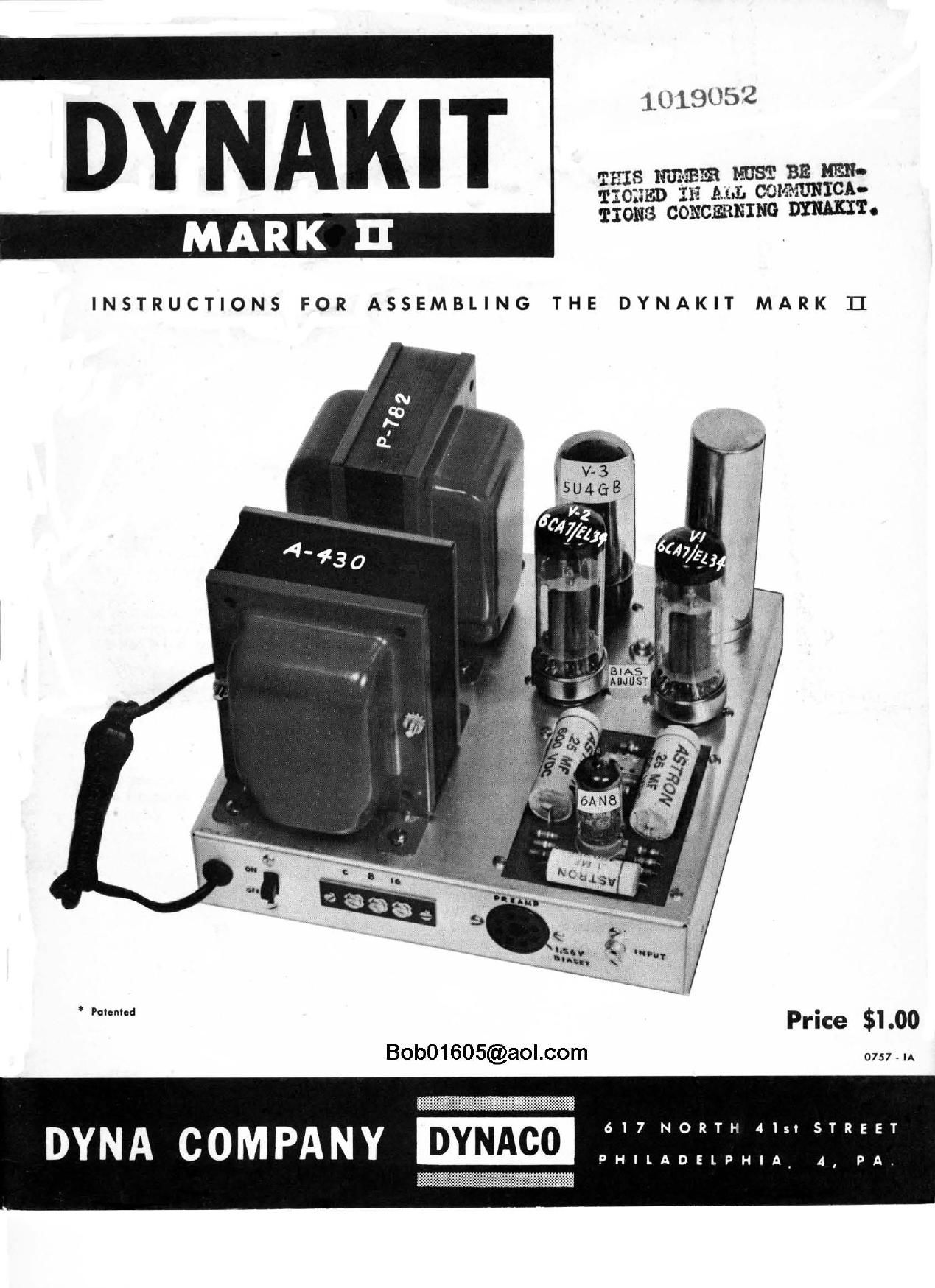
Dynaco Dynakit Mark II Owners Manual

This is the 15 pages manual for Dynaco Dynakit Mark II Owners Manual.
Read or download the pdf for free. If you want to contribute, please mail your pdfs to info@audioservicemanuals.com.

Page: 1 / 15
left right
Dynaco Dynakit Mark II Owners Manual

Extracted text from Dynaco Dynakit Mark II Owners Manual (Ocr-read)


Page 1

DY N A K I T 1.019052
' - . a-IBZ'B MIST BE ME-
iggfigvlil Ah!) CGMHUNICA-

T101153 CONCERNING mm'r.

INSTRUCTIONS FOR ASSEMBLING THE DYNAKIT MARK 1]

°'°"" Price $1.00
Bob01605@aol.com 0757 m

COMPANY DYNAco iTTET

Page 2

Power Output

lntermodulation
Distortion

Frequency
Response

Power Response

Square Wave
Response

Sensitivity

SPECIFICATIONS

50 watts continuous, 100 watts
peak.

Less than 1% at 50 watts; less
than .5% below 35 watts. These
figures apply for any conven-
tional combination of test fre-
quencies.

i .5 db 6 cps to over 60 kc.

1 .1 db 20 cps to 20 kc at any
level between I milliwott and 50
watts.

20 cps to 20 kc within 1 db of
50 watts without exceeding 1%
harmonic distortion over this
range.

Essentially undistorted 20 cps to
20 kc on loudspeaker load.

1.5 volts rms input for 50 watts
output.

Hum and Noise
Damping Factor

Output im pedances

Tu be:

Size

Weight

Pre-Amp Provision:

Bob01605@aol.com

80 db below rated output.
l5.

8 and 16 ohms (no restrapping
required for changing output im-
pedances.) (Choice of 4, 8, and
16 ohms also available at extra
cost.)

6CA7 EL-34 (2), (6550s can be
substituted in output without
wiring changes), 6AN8, 5UAGB.

9 by 9" by 6%" high.

27 pounds.

Any pre-amp can be used. For
pre-amps without power a spare
socket is included which permits

drawing 200 to 450 volts dc at
20 mo and 6.8 volts ac at l amp.

Page 6

former:

(
(

washers.

)
)

Please note on pictorial diagram #1 the identification of
the various parts and their respective terminal numbers. These
identifications will be us ed when specifying connections.

Make the following connections from the output trans-

l.

2.

8.

Connect blue wire to pin 3 of V2 (S).
Connect green wire to pin 4 of V2.

Connect blue-white wire to pin 3 of V1 (S).
Connect green-white wire to pin 4 of V1 (S).
Connect red wire to condenser lug 2.
Connect yellow wire to screw terminal 3.

Connect orange wire to screw terminal 2 (S).

(If the 4 ohm Dynakit is being assembled, the brown
wire is the 4 ohm lead. It should be connected to
screw terminal 2 (S). The end of the orange wire
should be taped and this lead left loose inside the
chassis. With this arrangement the output impedances
are 4 and 16 ohms. A shift to 8 and 16 output can be
made at any time by interchanging orange and brown
leads).

Connect black wire to screw terminal 1.

Mount P-782 transformer with #3 screws, nuts and lock-
See pictorial diagram #1 for correct orientation of trans-
former lead colors below the chassis.

Make the following connections:

1.

Connect long black wire to switch lug l (S).
Connect short black wire to lug terminal 1.
Connect one red wire to pin 4 of V3 (5).
Connect another red wire to pin 6 of V3 (S).
Connect one yellow wire to pin 2 of V3 (S).
Connect another yellow wire to pin 8 of V3.
Connect red-yellow wire to lug terminal 3.
Connect red-black wire to positive lug on

selenium rectifier (S). This is the lug
nearest the chassis.

, Twist the two green wire tightly together and

connect one to pin 2 and the other to pin 7 of V2.

Bob01605@aol.com