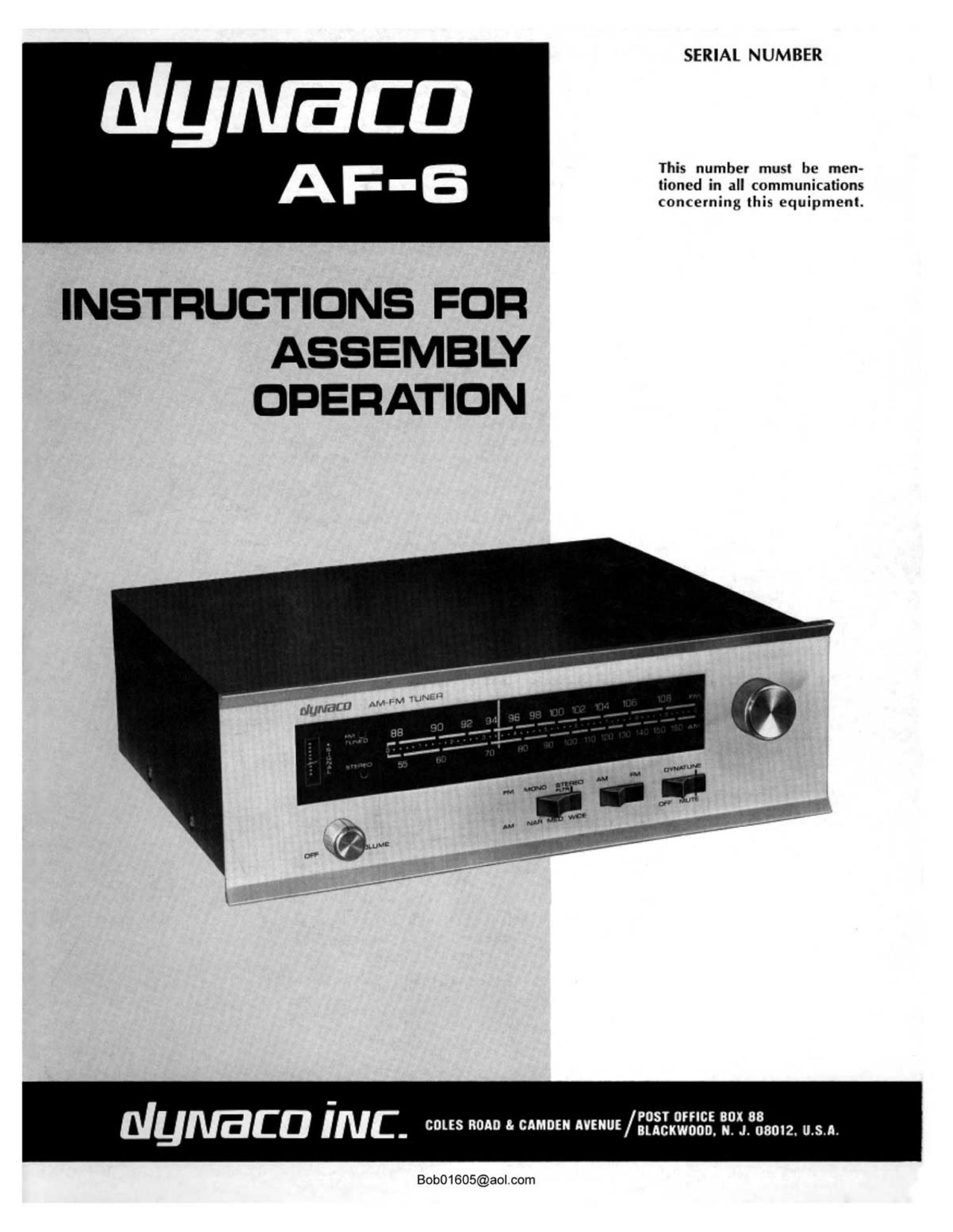
Dynaco AF 6 Service Manual

This is the 31 pages manual for Dynaco AF 6 Service Manual.
Read or download the pdf for free. If you want to contribute, please mail your pdfs to info@audioservicemanuals.com.

Page: 1 / 31
left right
Dynaco AF 6 Service Manual

Extracted text from Dynaco AF 6 Service Manual (Ocr-read)


Page 1

SERIAL NUMBER

This number must be men-
tioned in all communications
concerning this equipment.

INSTRUCTIONS FOR
ASSEMBLY
OPERATION

NUIVBCD iNC. cm 0 " "0" ""uE/zfflxflg'fi méfism. u.s.n.

Bob01605@aolcom

Page 2

FM SPECIFICATIONS

IHF sensitivity (noise and distortion down 30 dB @ 100%
modulation): 1.75 v.
Input required for 40 d0 SIN 100% modulation: 2.0 pv.
Input required tor 50 dB 5/ N @ 100% modulation: 5.0 pv.
Frequency response before de-ernphasls: 20 Hz to 52 kHz,
:1 d8.
De-entphasis time-constant: 75 psec.
Frequency Response: 20 Hz to 15 kHz : 1 dB
Harmonic distortion and IM distortion @ 100% modulation:
Mono-0.5% (0.25% typical].
Stereo-0.9% (0.5°/o typical).
Capture ratio: 1.5 dB.
Muting threshold: 4 uv.
Output @ 100% modulation: 2 volts.
Ultimate signal to noise ratio: 65 d8 @ 100% modulation.
Drift: less than 0.02%.
Selectivity: 65 dB alternate channel.
AM suppression: 58 dB.
Stereo switching threshold: 4 pV.
Stereo separation: @ 1000 Hz, 40 dB.
@ 50 Hz, 30 dB.
@ 10 kHz, 30 dB.
19 1:111 and 38 kHz subcarrier suppression: 50 dB minimum
67 I012 SCA carrier suppression: 80 dB minimum.

AM SPECIFICATIONS

Sensitivity: SO microvolts with external input.
Selectivity: 20 dB @ 10 kl-lz.
55 dB @ 20 kHz.
Image lteiection: 60 dB.
Total Harmonic Distortion: less than 2%.
IF Reiection: 70 dB @ 1000 kHz.

Antenna Provisions: 300 ohm balanced and 72 ohm un-
balanced external FM inputs; built-in AM
ferrite loopstick; external AM input and
ground connection.

Control Provisions: PowerNolume; Tuning; AWFM switch;
FM Tuning switch [mute off/mutingmuting
with Dynatune); mode switch [mono/stereo
filter/stereo FM, or narrow! medium/wide AM
bandwidth).

Dimensions: 13%" x 12" x 4'14" High.

Shipping weight: 13 lbs.

Power consumption: 12 watts, 120V or 240V, 50/60 Hz AC.

Bob01605@aol.com

Page 5

AC line Connection

The AF-6 is normally wired for the U5. standard 120
volt, 60 H7. AC line. Alternative wiring to accommodate
240 volt operation. at either 50 or 60 Hz, is described later
in this manual. Typically the tuner will be plugged into a
switched outlet on the control center or amplifier. Then the
tuncrs power switch may be left on at the volume setting
which matches other program sources. The AC outlet on
the back panel of the AF-6 is controlled by the front panel
switch. Thus if no separate control center is needed in your
system. the power amplifier may be switched through this
outlet, and the AF-G plugged into a wall outlet.

Antenna Connections

Four screw terminals are provided on the back panel for
external AM and FM antennas. A twinlcad folded dipole
FM antenna is supplied with the tuner, which will be ade-
quate for most l0cations. It should be connected to the
two screw terminals nearest the line cord. Suggestions on
FM antenna applications will be found in a later section of
this manual. entitled Getting The Most From Your FM
Tuner." Other FM antennas using the same type of flat
wire lead-in are also 300 ohm systems. and are connected to
the same terminals. Shielded 300 ohm lead-in (3 wires)
connects the shield to the (second) GND terminal, and the
signal leads to the right hand terminals.

Shielded coaxial cable used in many distribution systems
provides a 72 ohm unbalanced lead-in. It may he directly
connected without a matching balun transformer. The
shield connects to the GND terminal. and the center con-
ductor to the adjacent screw terminal on the right.

The high efficiency ferrite Ioopstiek AM antenna mounted
on the back panel will suffice in all but the most critical
situatious. Its pickup capability can be limited by nearby
metal surfaces, so it is important that the antenna bracket
be swivcled outwards so that it is at right angles to the
panel. Then swing the tubular antenna to the position
which provides the quietest signal. The best AM antenna
orientation is determined by the quality, not the strength
of the signal. Because AM reception is so susceptible to
local interference sources (which electrically resemble the
desired broadcast signal), and the wide frequency response
of the AF-G can make such noise effects very apparent,
proper positioning of the antenna for lowest noise is most
important.

Interference may be transmitted by the AC power line.
or it may be radiated by appliances. oil burners. fluorescent
lights, lamp dimmers, etc. The radiated effects can be
minimized by antenna placement. In special circumstances.
as when the tuner is mounted face up in a cabinet. the
usual adjustment is limited. Thus an extra hole is pro-
vided in the back panel which enables the antenna bracket
to be mounted alternatively at right angles to the cover.

Where optimum AM reception is important, an external
long wire AM pickup which is carefully insulated from
ground should be connected to the left screw terminal, and
it is used in conjunction with the loopstick. A separate earth
ground should then be connected to the GND terminal.

Output Connections

A pair of shielded cables is supplied with the AF-fi. These
should be connected front the AUDIO OUT tuner sockets
to the FM-MPX, RADIO or TUNER inputs of the contwl

center or amplifier. The output level of the AF-G is ad-
justed by the front panel volume control. The nominal out-
put level at maximum rotation from a fully modulated signal
is 2 volts at 1000 ohms output impedance. Thus you can
also connect the tuner directly to any basic power amplifier
which has an input sensitivity of less than 2 volts for full
output.

The out ut level of the TAPE OUT sockets is also ad-
justed by t e volume control. These may be connected to
the line inputs of a tape recorder.

Oil / Volume Control

The power switch, which also controls the back panel AC
outlet, is a part of the volume control. If the tuner is
plugged into a switched AC outlet on the control center,
the tuners volume control will likely be left in the upper
half of its range, where the tuner level will match the evel
of other inputs to the control amplifier.

Mono / Stereo / AM Bandwidth Switch

FM functions are identified above the switch. The normal
switch position is depressed to the right. The tuner switches
FM automatically from mono to stereo Operation, and lights
the STEREO indicator whenever the tuned station is broad-
casting the IQ kHz multiplex stereo pilot carrier signal.

In the middle STEREO FILTER position, high frequency
separation of stereo broadcasts is reduced, or blended, and
the high frequency response is rolled off 4 db @ 10 kHz to
improve the signal-to-noise ratio on weak stereo signals.
In other respects tuner operation is similar to the normal

STEREO mode.

In the MONO position all stations will be heard mono-
phonically and the stereo indicator will never light. This
position may provide greater clarity in monophonic recep-
ti0n of very weak stereo broadcasts.

Without the stereo pilot carrier, the tuner reverts to mono
operation automatically. However, stereo tuner charac-
teristics dictate that lower noise will be obtained in the

MONO switch position.

AM audio bandwidths are indicated below the switch.
The normal position is the middle MEDium setting, which
is similar to most other tuners in audio quality.

The WIDE position extends the audio range, and will
result in notably more accurate reproduction where the
signal quality and freedom from interference warrants it.
However. a strong signal does not necessarily justify the
WIDE position for best listening. Noise or unfavorable
broadcast quality may contribute to less pleasant sound in
this mode. Some AM signals are handicapped by high fre-
quency boost or excessive distortion.

The NARrow position sharply attenunates the high fre-
quency reSponse for satisfactory reception in high interfer-
ence conditions.

You should not be sur rised if local conditions make it
impractical to use the IDE position, f0r nearby wiring,
appliances and mechanical devices, as well as atmospheric
conditions, can all have adverse interference effects. Re-
location to avoid fluorescent lamps, light dimmers, etc.,
installation of line interference filters (usually most effective
at the offending appliance). or a good external antenna
and grOund connection may prove beneficial where the best
AM reception is important.

Bob01605@aol.com 5