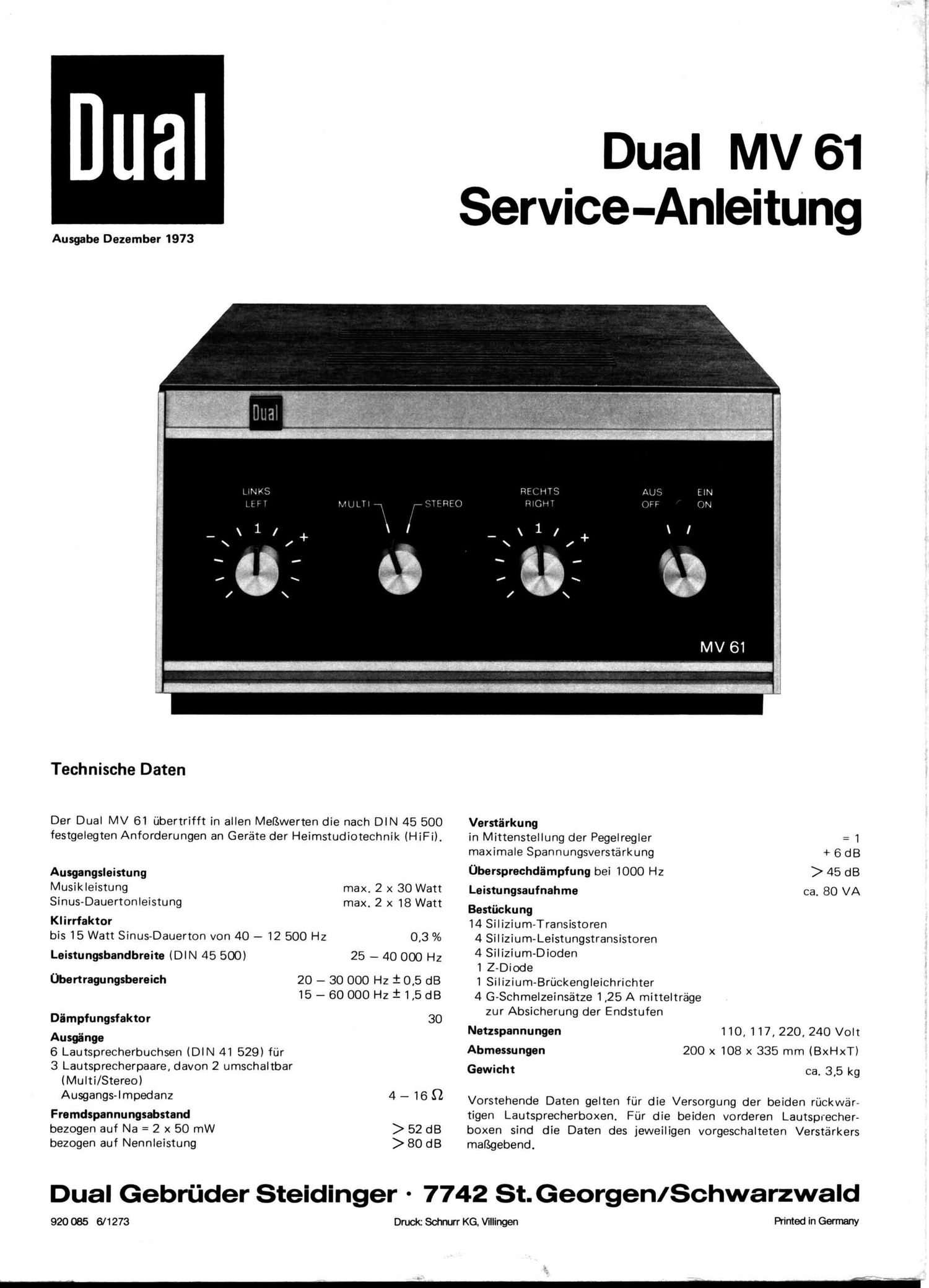
Dual MV 61 Service Manual

This is the 8 pages manual for Dual MV 61 Service Manual.
Read or download the pdf for free. If you want to contribute, please mail your pdfs to info@audioservicemanuals.com.

Page: 1 / 8
left right
Dual MV 61 Service Manual

Extracted text from Dual MV 61 Service Manual (Ocr-read)


Page 2

Fig.

9 4 1 o
R
1 K
C16 C:
10011-1"
M
Y a 4
R10 R11. R22 7 R41
560K 10K 3.3K N Hf 4 1.5K
2']. 2% _ 0 '
R1 R 18 T12 : 11
5.6 K . Es-vb 15.9K BC 253 B I
V c 10 2 '1 :32ij :
1 110 1' i _
A < 6 fl f I
1/7 R3 P1 links chc {32% c1". " i .-_
SK 1K left 259. 1 P . 152? X
' I
. Pegelregler gauche m | /
L 1- Level control -12 : R7112 =91
Régulateur de r"-"= p
- R11 R15 -1 R23 R25 I 5
we 150KB 1.7K P flaw 220K :
2'/. 2 'l. 1
I
l
l
51 1:12 ' -
- Pegelregler 2 0/. 110/ 117 V 1A
. Level control _ 220/ 240V 0.51
Régulateur de niveau rechts m;- 1?
B P2 right (:11
SK // < o 4 o
ELL- - "-0 1 '
I530? K R13 R17 '1 c1 .1.
' 1.7OK 10K _j _o\, SOn 1-
2']. $2
110... ZLOVV
4
R10 R11. R18 R22 R27 RL2
R R1 R3 P1 R11.R12 R15,R16 R20 R23 R25 R11
R2 R1. P2 R13 R17 R19 R21 R21. R26 R40 C R43
16
C (:10 012 011. 01.0 01.1
C 11 C 13 C 15 C1
. Verstc'irkugqseinstellung der Endstufe Transistoren von der Anschlufiseite gesehen. Sp
C110 und CAOI miteinander verbinden und 1kHz, 0,2V am Verstarkereingang (C 1.0,CLO') einspeisen. Transistors as 5" from the connectlng s'de- V'
Mit R 45 gleiche Verstarkung beider Kana'le elnstellen. 0115151015 VUS dU cbte laterale. Vc
2. Abfigleich der Eingangsspannungsteilers B K E St
Betriebsartenschalter in Stellung STEREO, P1 und P2 in Mittenstellung(Rastung). Am Eingang E Cl
1kHz ca. LV einspeisenBeide Kanale mit den Reglern R 3 und RI. auf Verstarkung=1abgleichen @ C0

1. StrenLthening adjustment of the output stgge.

Connect C110 and C40' together and feed to the amplifier inputh40,Cl.0')1kHz, 0,2 V.
With the RAE boost both channels accordringly.

2. Adjustment of the Input Potentiometer

Set on STEREO, P1 and P2 in middle position (notch). Feed to input lkHz about 4V. Increase both
channels with the adjusters R3 and R1. results in 1 adjustment.

1. Réglage de l'amplification de létage de sortie

Relier C40 etC LO'entre eux et appliquer 1kHz, 0,2 V a l'entrée de lamplificateur (CLO, C 40').
Avec R45. regler la meme amplification sur les deux canaux.

2.Réfllage du diviseur de tension d'entrée

:: B
000 EofioK

E B K
BC 173C BC 2538

Amener le se'lecteur de mode de fonctionnement dans la position stéréo. P1 et P2 dans la position centrale (marque).

A l'entrée, appliquer 1kHz et environ AV. Avec R3 et RA. regler les deux canaux sur l'amplificationz1.