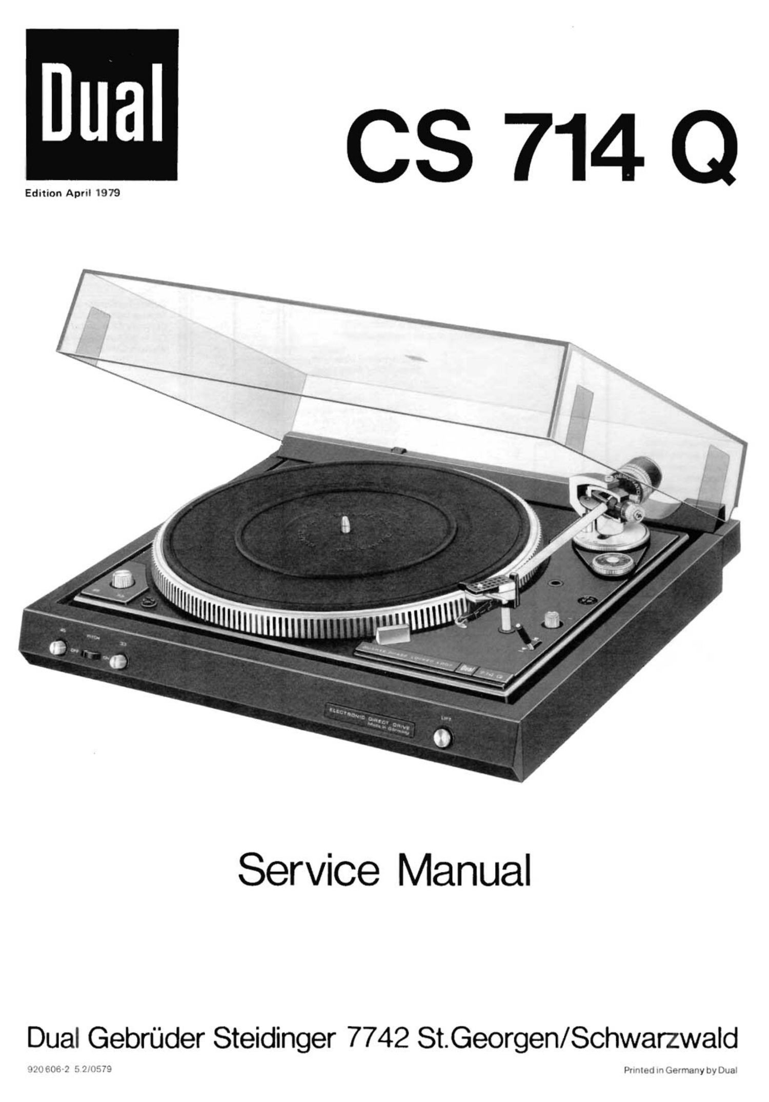
Dual CS 714 Q Service Manual

This is the 14 pages manual for Dual CS 714 Q Service Manual.
Read or download the pdf for free. If you want to contribute, please mail your pdfs to info@audioservicemanuals.com.

Page: 1 / 14
left right
Dual CS 714 Q Service Manual

Extracted text from Dual CS 714 Q Service Manual (Ocr-read)


Page 1

M 037140

Edition April 1979

Service Manual

Dual Gebrflder Steidinger 7742 St.Georgen/Schwarzwald

Punted In Germany by Dual

Page 8

4. Disengage tension spring (128), fastening disc (90) and remove
skating lever.

5. Remoiie hexagon nuts (94) and segment (124).

6. Hold tonearm (30). Remove hexagon nut (95); remove tone-
arm complete with tonearm mounting.

When installing the tonearm proceed in reverse order.

Replacing spring housing

Remove tonearm (30) from bearing frame (66) as described above.
During fitment, ensure that the spiral spring engages in the Cut-
out of the bearing (71). Fit tonearm (30) again. Set bearing play
as described below using threaded pin (65) and lock nut (61).

Adjusting the tonearm bearing

First balance tonearm exactly, Both bearings must have slight,
just perceptible play. The horizontal tonearm bearing is correctly
adjusted when at anti-skating setting "0.5" and being t0uched, it
Slides in without resistance. The vertical tonearm bearing is cor-
rectly adjusted when it swmgs in after being touched. Play of the
horizontal tonearm bearing should be adju5ted wrth threaded pin
(62), play of the vertical tonearm bearing with threaded pin (65).

Antiskating device

Adjustment of the anti-skating force is carried Out by turning the
knurled ring on the cover. According to adjustment the asymme-
trical cam disc guides the skating lever (134) out of the tonearm
pivot point. The anti-skating force is transmitted to the segment
(124) by means of tension spring (136) and so to the tonearm.
Optimum adjustment is carried out at the works for styli with a
tip radius of 15 um (cenical). and 5/6 x 18/22 um (elliptical) as
well as for CD 4 cartridges.

Any alteration can only be carried Out with the aid of a Dual
skate-O-meter and a test record and should only be done by a
Dual authorized service station.

Cue control

By moving lever (187) forward (1) lift cam (I88) rotates. The
slide bar (168) connected to it transmits this movement to the
lift pin which then raises the tonearm.

As a result the tonearm can be lifted off and set down on a record
at any desired point outside the shutoff range.

The slide bar (187) is released by moving the cue control lever
back (1). As a result of the action of the compression spring the
lift pin is returned to neutral position and thus lowers the tone-
arm. Lowering of the tonearm is damped by the silicone oil in
the lift tube.

Height of the stylus above the rec0rd can be varied by the pre
tension of the compressmn spring of the lift plate (176). Accor-
ding to operation of the adjusting ring (82) in "4" the lowering
speed is reduced, in position " «4 " it is increased.

Adjustment point

The lift height is varied by turning the adjustment sleeve (187).
The distance between record and stylus should be approximately
5 mm.

Replacement of the cue control plate

Replace cue control plate complete (187) as follows:

1. Fix unit on repair jig and lock tonearm. Turn unit upside
down.

2. Remove fastening disc (89) and disc (175) as well as bearing

(174). Lift adjusting bar (173) and swivel to short circuiter
(120).

3. Remove both fillister head cap screws (96). Remove cue

control plate (188).
4. RemOve hexagOn nuts (94) and segment (124).

When fitting proceed in reverse order. It should, however, be en-
sured that the pressure piece of the cue control plate (188) enga-
ges correctly in adjusting ring (82). (Varying the lowering speed).