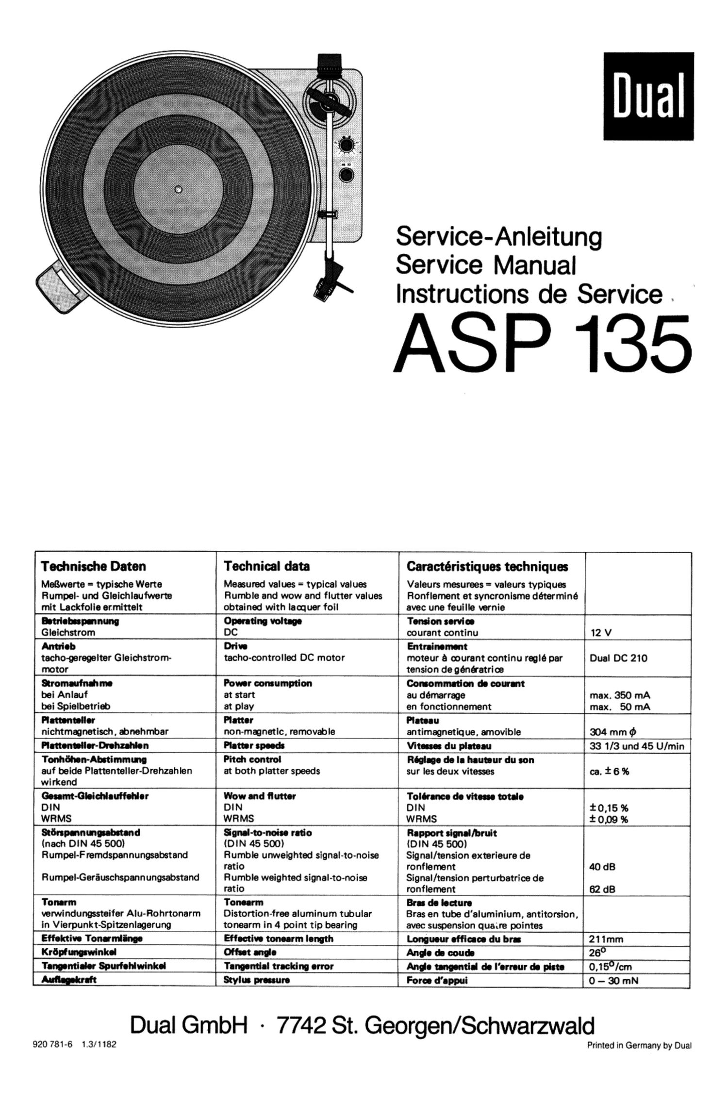
Dual ASP 135 Service Manual

This is the 6 pages manual for Dual ASP 135 Service Manual.
Read or download the pdf for free. If you want to contribute, please mail your pdfs to info@audioservicemanuals.com.

Page: 1 / 6
left right
Dual ASP 135 Service Manual

Extracted text from Dual ASP 135 Service Manual (Ocr-read)


Page 1

Service-Anleitung
Service Manual
Instructions de Service

ASP 135

Teohnieohe Daten

MeBwarta - typisohe Warta
Rumpel~ und Glelchlaufwerte
mIt Laokfolle ermlttelt

Technical data

Measured values - typical values
Rumble and wow and flutter values
obtained with lacquer foil

Caractéristiquee techniques

Valaurs mesunaas = valeura typiquee
Honflamam at syncronlsme determine
avac una faullle varnie

Wet-puma Operating voltage Tension «Ma
Glelchstrom DC courant oontinu 12 V
Antrieb Drive Entrainement
techo-gareoaltar Gleichstrom tacho-oontrollad DC motor moteur a murant continu raolé par Dual DC 210
motor tension de génkatrloe
monarch-dune Power cor-umptlon Commutation de pour-rt
bei Anlauf at start au damarrage max. 350 mA
bai Spielbetrid) at play en fonctionnement max. 50 mA
Plattermler Platter Plateau
nichtmmnatisoh, danehrnbar nonmmnetlc. removable antimagnetique, arnovible 304 mm ¢
"Mar-Drama Platter speeds Vltaaeee du plateau 33 1/3 und 45 U/rnin
TonlIflIen-Ahatimmmo Pitch control Reine de la heuteur du eon
auf belde PIattenteller-Drehzahlen at both platter speeds sur les deux viruses ca. 1: 6 96
wlrkond
Geearm-Gleiddauflefler Wow and flutter Tolerance de vlteeae tetale
DIN DIN DIN 10.15%
WRMS WFIMS WRMS 1' 0,09 96
salami-inbound Smal-to-noiee redo Rapport denaIIbrult
(nach DIN 45 500) (DIN 45 500) IDIN 45 500)
Rumpel-Fremdspennunosebatand Humble unweighted signal-to-noise Signal/tension extarlaure de

ratio ronflement 40 dB
Rumpel-Geramchspmnungsabstand Humble weighted signal-to-noise Signal/tension perturbatrioe de

ratio ronflernent 62 d8
'l'onarm Toneerrn Brae de lecture
verwlndungssteifer Alu-Rohrtonarm Distortion-free aluminum tubular Bras en tube d'aluminium, antitorsion,
In Vierpunkt-Spitzanlagerung tonearm in 4 point tip bearing avec suspension quaire pointes
Effektive Tmnflnae Effective tomarm length Lonnueur effleaoe du hm 211mm
Krdphat'wlnkel Ofleet Ilia Ande & ooub 28°
Tanputlder Spuriohlwinkd Tangential traoldnu error Ange Md de l'erreur de plate 0,156/cm
m Wm praaeure Force d'appui 0 - 30 mN

Dual GmbH ~ 7742 St. Georgen/Schwarzwald

920 781-6 1.3/1182

Printed in Germany by Dual

Page 2

Motor und Antrleb

Der Antrleb des Plattentellers und der Kinematik erlolgt durch den tachogeregei-
ten Gleichstrommotor Dual 00 210.

Elnetollen der Nenndrehuhlen

1. Stellar (Pitch) in Mittelsteliung bringen.

2. Drehzahlumschalter in Stellung .33 mil R 9004 Nenndrehzahi 33 1/3 U/min
einstellen.

3. Drehzahlumschaiter in Stellung .45' mit R 9005 Nenndrehzahl 45 U/min
einstellen.

WHO!

Der Plattenteller 3 ist mit der Tellersicherung 4 gesichert. Zum Abnehmen des
Piattentellers 3 die Tellersicherung 4 seillich abziehen.

Antrlebotellor

Zum Austausch des Antriebstellers 7 sind der Flachriemen 6. die Sechskantblechv
schrauben 31 und die Lagerbrt'icke 30 zu entlernen.

Tonarm und Tonarmlagerung

Auebeu doe Tonarmeo kpl. mit Tonermlagorung

Es empliehlt sich wie ioigt vorzugehen:

1. Tonarm 55 verriegeln. Gewicht 44 entlemen.

2. Tonarmieitungen an Anschlqulatte 11 abldten.

3. Haupthebel 95 abnehmen. Die Steilschraube 41 drehen bis FUhrungslager
100 und Stellschiene 105 irel sind. Zugleder 106 aushangen. Stellschiene
105 zur Lagerbn'icke schwenken.

4. Zugieder 113 aushiingen. Die beiden Zylinderschrauben 116 entfernen.
Tonarm 55 lesthalten. Segment 114 entlemen. Tonarm abnehmen.

Der Einbau erlolgt in umgekehrter Reihenlolge.

Austausch dos Ton-rm»

1. Tonarm 55 verriegein. Gewicht 44 entternen.

2. Tonarmieilungen an AnscthBplatte 11 abloten.

3. Sicherungsscheibe 45 an der Lagerspitze 46 entiemen. Lager 46 gegen die
gelederte Lagerspltze 46 driicken. so daB der Tonarm 55 nach vorne aus dem
Lagerrahmen 47 entnommen werden kann.

Der Einbau erfolgt in umgekehrter Reihentolge.

Tonarmlift

Auetausch doe Llftrohn

1. Tonarm kpl. mit Tonarmlagerung ausbauen.
2. Die Sicherungsscheibe 43 entiernen. Liltrohr kpl. 34 abnehmen.

Der Einbau eriolgt in umgekehrter Reiheniolge.

Justagepunkte

Abatellpunitt

Der Abstellpunkt (Abstellbereich Flatten Q 125 - 1 15 mm) kann durch geringlligi-
ges Biegen der Absteilschiene 20 verandert warden.

Tonarmlltt

Die Llithohe lab! sich durch Drehen der Steiischraube 41 verandem. Der Abstand
zwischen Schallplatte und Abtastnadel soil ca. 5 mm belragen.

Bowdenzug Start/Stop

Bei gedrflckter Startlaste soil zwischen Umschaltwinkel 90 und Startschieber 24
ein Uberhub von ca. 0.3 mm vorhanden sein. Justierung mil Randelmutter R.
vornehmen.

Bowdenzug Lift

Bel Betatigen der Liittaste 2 soil ein Spiel von ca. 0.5 mm zwichen Hubstiick 101
und Grundplatte 12 vorhanden sein. Justieren mit R'éndelmutter R, vornehmen.

Motor and Drive

Power tor the turntable platter and the changing mechanism is supplied by a tacho
controlled DC motor Dual DC 210.

Adjustingtherltedspeod

1. Set the control (pitch) in central position.

2. Set speed control switch in position .33 with R 9004 adjust the rated speed
33 1/3 Ulmin.

3. Set speed control switch in position .45' with R 9005 adjust the rated speed
45 U/min.

Plotter

The platter 3 is secured with the locking spring 4. When removing the platter 3 to
detach the locking spring side ways from the spindle.

Flywheelrotor

When you replaced the fly wheel rotor 7, you remove the flat belt 6. the screws 31
and the bearing bridge 30.

Tonearm and tonearm bearing

Dismantling the tonearm complete with the tonearm bearing.

We recommend the following procedure:

1. Lock the tonearm 55 in rest position. Remove the weight 44.

2. Unsolder the tonearm connections at the connection plate 11.

3. Remove the main lever 95. Turn the adjusting screw 41 until the guide bearing
106 and arm positioning rail 105 are free. Remove the spring 108. Swing the
arm positioning rail 105 onto the flywheel rotor bearing assembly.
Disengage the tension spring 113.

Remove both hexagonal screws 116. Grip the tonearm 55. Remove the
segment 144. Remove the tonearm.

S"?

Reassembly involves the reverse procedure.

Changing the tonearm

1. Lock the tonearm 55 in rest position. Remove the weight 44.

2. Unsolder oil the tonearm connections at the connection plate 11.

3. Remove the locking washer 45 an the Bearing point 46. Press the bearing 46
in the direction 01 the spring bearing point 46, so that the tonearm 56 may be
removed (mm the lront of the bearing trams 47.

For reassembly lollow the reverse procedure.

Cue control

Changing the litt tube

1. Dismonlling the tonearm complete with the tonearm bearing.
2. Remove the lock washer 43. Remove the complete lift tube 34.

Reassembly involves the reverse procedure.

Adjustment points

Switch of! point

The switch 011 point (switch oil range record D 125 - 115 mm) can adjusted by
slight bending the shutt-oii rail 20.

Toneerm lift
The lift can be varied by turning the adjustment screw 41. The distance between
the record and the needle should be approx. 5 mm.

Start/Stop Bowden cable

Play of approximately 0.3 mm should exist in the switch over bracket 90 oi the start
slider 24 when start button is activated. The play can be adjusted by the knurled
ring R,.

Lift bowden cable

Play of approximately 0.5 mm should exist in the lift piece 101 of the base plate 12
when button 2 is activated by the limit stop. The play can be adjusted by the knurled
ring 8,.