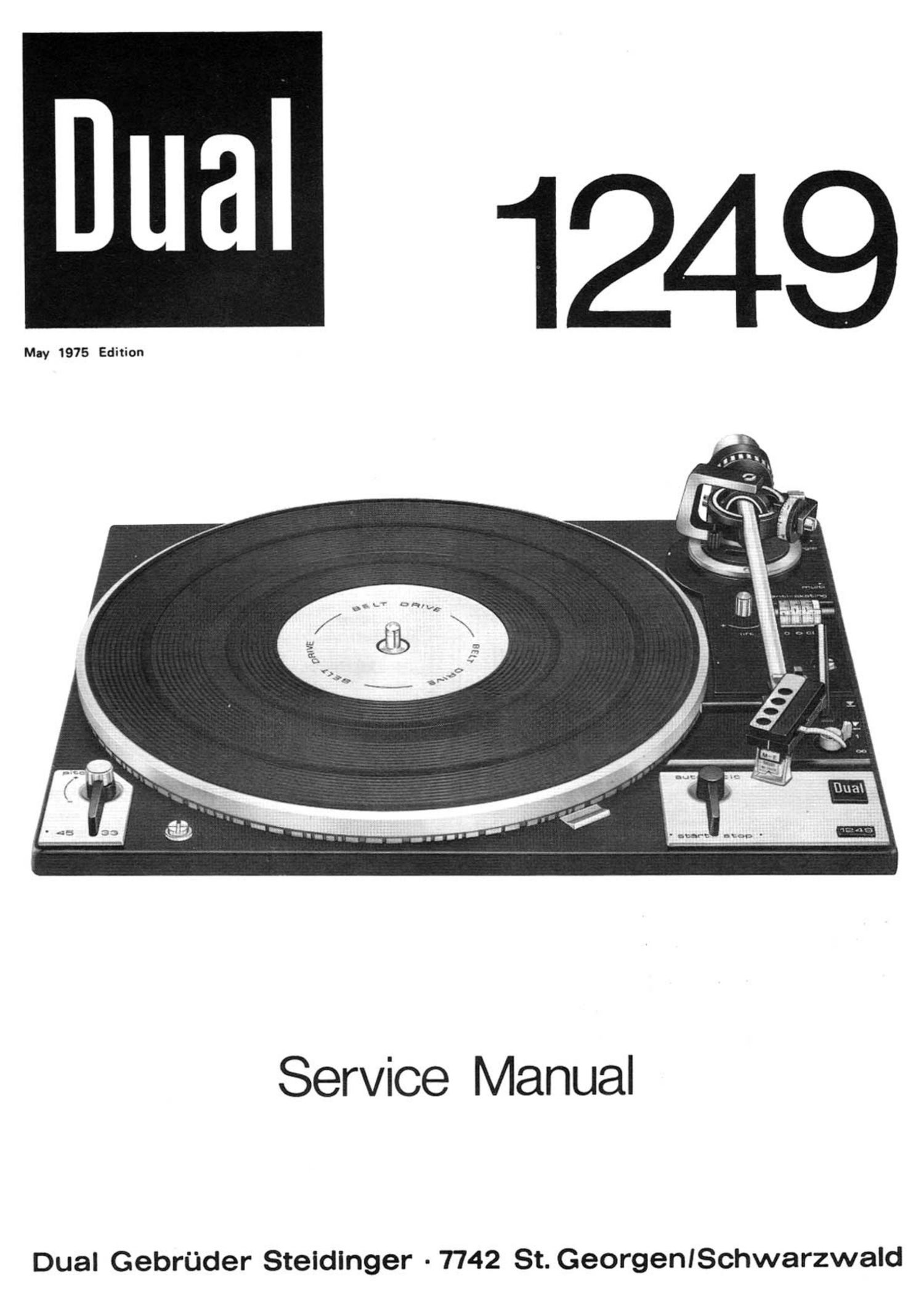
Dual 1249 Service Manual

This is the 20 pages manual for Dual 1249 Service Manual.
Read or download the pdf for free. If you want to contribute, please mail your pdfs to info@audioservicemanuals.com.

Page: 1 / 20
left right
Dual 1249 Service Manual

Extracted text from Dual 1249 Service Manual (Ocr-read)


Page 1

May 1975 Edition

Service Manual

Dual Gebrflder Steldinger -7742 St. GeorgenISchwarzwald

Page 7

Tonearm and Tonearm Bearing

The Dual 1249 has a feather-light, extremely
torsion-resistant all-metal tonearm which is
suspended in a gimbal. Suspension is by
means of 4 hardened and precision polished
steel points which rest in precision ball
bearings. Tonearm bearing Friction is thus
reduced to a minimum.

Bearing friction vertical § 0,07 mN 0,007 p)
Bearing friction horizontal é 0,16 mN 0,016 p)

related to stylus point.

As a result, it ensures extremely favourable
pick-up conditions. The pick-up head is re-
movable. Before adjusting the pick-up force
to suit the built-in pick-up cartridge the
tonearm is balanced with the scale set to 0.
Coarse adjustment is carried out by moving
the counterweight (70) with stem, the sub-
sequent fine adjustment by turning the pre-
set disk of the counterweight. The balan-
ce weight is designed so that pick-up cart-
ridges with a deadweight of 4,5 - 10 9 can
be balanced. For the absorption of vibra-
tion and rapid small shocks the counter-
weight is flexibly connected to its threa-

ded stem.
The pick-up head is suitable for accommo-

dating all pick-up cartridges whose type

of mounting conforms with the interna-
tional standard 1/2 inch mounting and whose
deadweight does not exceed 10 g. The track-
ing force is adjusted b turning the gradu-
ated spring housing (78 and thus tensioning
or releasing the coil Spring mounted inside.
The scale has markings from 0 - 30 mN

(0 - 3 p) to define the range of adjust-
ment. An exact setting is possible from

2 - 15 mN (0,2 - 1,5 p) for the required
tracking force of 1 mN (0,1 p), for the
range of setting of 15 - 30 mN (1,5 - 3 p),
from 2,5 mN (0,25 p) to 2,5 mN (0,25 p).

To change the tonearm complete with ton-
earm suspension we recommend preceeding

as follows:

1. Secure unit in repair jig and arrest
tonearm.

2. Move unit into head position and unsol-
der tonearm leads.

3. Remove main lever (194).

4. Unhinge tension spring (239), loosen
lock washer (245) and remove skating
lever complete (248).

5. Remove lock washer (188) and sliding
washer (187). Take off shut-off bar
(182) from segment (240).

6. Remove lock washer (251, unhinge
tension spring (196). Turn setting
screw (66) until pivot bearing (252)
and slide bar (253) are released.
Take off lock washer (259) and slide
bar (253).

7. Remove machine screw (222) and curb
(220). Take off lock washer (58) and
segment (240).

8. Loosen machine screw (231) and unhinge
leaf spring (232) of lift pin (51).

9. Place turntable in normal position.
Set adjusting curve (633 to position
"multi", turn frame 54 of tonearm hear-
ing anti-clockwise till stop gauge. Re-
move tonearm with bearing.

To reinstall tonearm complete with bearing

carry out mounting in reverse order.

Attention: Dont forget to install compres-
sion spring (61).

To remove the tonearm from the bearing rack
(72) the tracking force scale should first
be set to zero position after unsoldering
the tonearm leads. RemOVe counterweight
(70). Turn both setscrews (74) into ton-
earm till stop gauge.

Attention: Bayonet mounting!

Push tonearm backwards and take it out of
bearing rack (72). Assembly in reverse or-
der.

For adjusting the tonearm head, a hole is
provided in the chassis to make this pos-
sible without first removing the tonearm
(Fig. 10).

Adjustment of Tonearm Bearing

Both bearings must have slight, just per-
ceptible play. Adjustment of the vertical
bearing should only be carried out by means
of the left mounting screw (grub screw 55),
that of the horizontal hearing by means of
grub screw (52). The horizontal tonearm
bearing is correctly adjusted when at
antiskating setting "0.5" (tonearm pre-
viously balanced exactly) the tonearm
slides in without resistance.

Fig. 11 Tonearm bearing assembly
- 53
54 ~~~~~~ -- 52
78
56 .. ( i ,th ,1 . ._._ 79
55~w-w _ y
77 -~~--- ---- "\\ 1,),
\~ 72
x\:\\\ \k\._ , __ . .- 60
63 --- -» - _ ___.- 6,
4o ___m~__62
240 7 . 64
sz-~- - - ~ \ ~-~ um-w- 65
243-~---~ ~ i;
. ___ ____________ w__ 58
\_. . _.--....7.-_- ._.. ..- ._,.....,_..__ 57
Fig. 12 Tonearm bearing assembly

(view from underneath)

248
240

253

194

Page 19

Poe. Part.-No.

Description

Qty.

221 234
222 210
223 234
224 223
225 210
226 234
227 201
228 210
229 210
230 234
231 210
232 210
233 230
234 234
235 232
236 234
237 203
238 210
239 218
240 236
241 234
242 216
243 211
244 229
245 210
246 230
247 210
248 234
249 234
250 223
251 210
252 229
253 234
254 210
255 234
256 234
257 234
258 236
259 210
260 225
261 236

C 1 225
C 2 224

D 1 225

R 1 232
R 2 232

262 236
263 210
264 232
265 214
266 232
267 231

*** 214
*** 229
*** 236
*** 236
*** 236
*** 236

663
472
026
777
145
673
184
283
607
664
472
587
087
598
545
593
477
353
591
915
658
845
718
688
146
456
586
549
665
146
145
362
670
145
674
669
700
916
146
321
917

322
886

247

402
401

918
469
996
602
995
079

120
321
920
328
434
257

Guide block 0 O O .0 O ... O O O. O O O. 0.. O. O I O .0 C. I. I O CO.
machine screw Am 3 x a .0 O O C .0 O. C C O. O O O C O C O U O 0..
Set Screw M 2.5 x a O. O D O O I 0.. O. O O O. O O O C C O U C. D. 0

Guide O.........OCOOOOOOOOOOOOOOOI.....IOIICOOI.

Lock washer 2.3 ................................
Distance track .................................
Adjusting washer ...... ....... .................
Fillister head screw B 2.9 x 6.5 ...............
Uasher 3.2/1o/o.s St ......................... ..
Lap joint ......................................
Machine screw AM 3 x 4 .........................
Uasher 2.2/7/1 .................................
Screw bolt .....................................
Connecting bus .................................
Leaf spring ....................................
Guide angle ....................................
Uasher 2.7/8/1 St ..............................
Hex nut BM 2 ...................................
Tension spring ........ ....... ..................
Segment ........................................
Hook spring ....................................
Rubber washer .. ............ ....................
Steel Ball 3 ...................................
U spring ............ .........................
Lock washer 3.2 ................................
Adjusting screw ................................
Uasher 3.2/7/0.5 St ............................
Skating lever compl. .......... ..... . ...... .....
Screw bolt ....................... ...... ...... ..
Fuse spring ....................................
Lock washer 2.3 .. ...... ........................
Guide bearings ................. ..... ...........
Slide bar ......................................
Lock washer 2.3 ................................
Brake section ..................................
Screw bolt For bruke section ...................
Strobe diaphragm ....... ..... ...................
Stroboscope housing ............. ...... ... ......
Lock washer 3.2 ................................
Glow lamp ......................................
Uiring board compl. ............................

Foil capacitor 68 nF/400 u/1o % ................
Foil capacitor 47 nF/2so u/zo % ......... .......

Silicon diode BY 183/300 ......COOCCIOOOIOOOOOI

Film resistor 22 k9/0.2s u/s % . ...............
Film resistor 12 kQ/OO125 U/5% OIIIUIOIOOIOOIOO

Cover (housing top) compl. .....................
Machine screw AM 3 x 3 .........................
Power cable Europe compl. . ..... . ........ .......
AMP connector ..................................
Power cable US compl. ..........................
Cable clips compl. .............................

Hardware for cartridge mounting ................
Packing carton 1249 compl. .. ...... .............
Packing carton CS 1249 compl. ..................
Mounting instructions ..........................
Operating instructions .........................
Operating instructions UAP .....................

..s._\_$_s_3_) JAN-50.4 ._\._\ ....) ...t_\ _)_\b-iAA-QQ-iAm-IdAb-fifigud-t-a-AA-Aa-dde-io-ig-ifimANaé

*** Not illustrated

19

Alterations reserved!