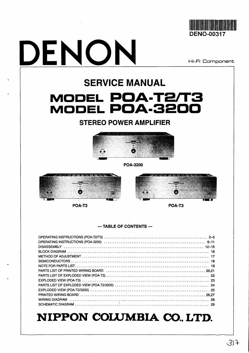
Denon POA T3 Service Manual

This is the 30 pages manual for Denon POA T3 Service Manual.
Read or download the pdf for free. If you want to contribute, please mail your pdfs to info@audioservicemanuals.com.

Page: 1 / 30
left right
Denon POA T3 Service Manual

Extracted text from Denon POA T3 Service Manual (Ocr-read)


Page 1

IIIIIIIIIIIIIIIIIMIIIIIIIII

BEND-00317

DE NON

em:

SERVICE MANUAL

MODEL FDA-Terra
MODEL FDA-3200

STEREO POWER AMPLIFIER

FDA-3200

POA-T2 POA-T3
- TABLE OF CONTENTS -

OPERATING INSTRUCTIONS (POA-T2fl3) ........................................................ 2-5
OPERATING INSTRUCTIONS (FDA-3200) ....................................................... 6-11
DISASSEMBLY ....................... . 12-15
BLOCK DIAGRAM ......... . 16
METHOD OF ADJUSTMENT . . 17
SEMICONDUCTORS ........................................................................... 18
NOTE FOR PARTS LIST ......... , ................................................................ 19
PARTS LIST OF PRINTED WIRING BOARD . . . 20.21
PARTS LIST OF EXPLODED VIEW (FDA-Ta) ....... . . 22
EXPLODED VIEW (POA-TS) .................... . 23
PARTS LIST OF EXPLODED VIEW (POA-TZ/SZOO) ................................................... 24
EXPLODED VIEW (POA-T2/3200) ................................................................. 25
PRINTED WIRING BOARD . . . I ' 26,27
WIRING DIAGRAM ............................................................................ 28
SCHEMATIC DIAGRAM ........................ I ................................................ 29

NIPPON COLUMBIA CO.. LTD.

313w

Page 17

_ FDA-W200 -

METHOD OF ADJUSTMENT

IDLE CURRENT ADJUSTMENT

0 Setup
1. Keep the unit away from direct wind blown by an air-conditioner and an electric fan, and keep the unit under normal
conditions. Adjust the range of ambient temperature to 15 - 30°C.
2. Set the following conditions as follows:
. 0 POWER (Power switch) to off

I SPEAKERS (Speaker Terminal) to no load (Speakers Disconnected)(.3ut SP-A SW to on.)
0 Disconnect input terminal

c Adjustment

1. Connect DC Voltmeter to Test points (TP101) of 1U-2909.

2. Turn POWER Switch ON.

3. Adjust VR102 so that the DC Voltmeter reads 2 i 0.5mV. '
4. Then after 3 minutes wam~up time, readjust VR102 so that the DC Voltmeter reads 2 i 1mV. :
5. Adjust each channel as same way above.

OFFSET ADJUSTMENT
oSetup

1. Keep the unit away from direct wind blown by an air-conditioner and an electric fan, and keep the unit under normal
conditions. Adjust the range of ambient temperature to 15 - 30°C.
2. Set the following conditions as follows:
0 POWER (Power switch) to off
0 SPEAKERS (Speaker Terminal) to no load (Speakers Disconnected)(,But SP-A SW to on.)
0 Disconnect input terminal

o Adjustment

1. Connect Speaker A terminal to DC Voltmeter and oscilloscope.

2. Adjust oscilloscope range to 5mV/div.

3. Tum Power Switch ON".

4. Adjust VR101 so that the DC Voltmeter reads 0- + 1mV

5 Then after 3 minutes wam- up time, readjust VR101 so that the DC Voltmeter reads 0- + 1mV.
6. Adjust each channel as same way above.

Radiator Plate

E!

D TP101
VFH 02 D

VH101

1U-2909 Power Amp. P.W.Board

17