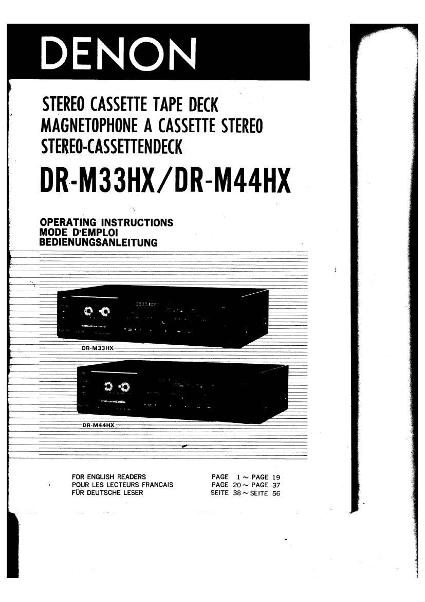
Denon DRM 33HX Owners Manual

This is the 19 pages manual for Denon DRM 33HX Owners Manual.
Read or download the pdf for free. If you want to contribute, please mail your pdfs to info@audioservicemanuals.com.

Page: 1 / 19
left right
Denon DRM 33HX Owners Manual

Extracted text from Denon DRM 33HX Owners Manual (Ocr-read)


Page 1

STEREO CASSETTE TAPE DECK
MAGNETOPHONE A CASSETTE STEREO
STEREO- CASSETTENDECK

DR- M33HX/ DR M44HX

OPERATING INSTRUCTIONS
MODE DEMPLOI
BEDIENUNGSANLEITUNG

Page 2

IMPORTANT TO SAFETY

WARNING :

TO PREVENT FIRE 0R SHOCK HAZARD, DO NOT EXPOSE THIS APPLIANCE
T0 RAIN 0R MOISTURE.

CAUTION:

1.

Handle the power supply cord carefully

Do not damage or deform the power supply cord. If it is damaged or deformed, it
may cause electric shock or malfunction when used. When removing from wall outlet,
be sure to remove by holding the plug attachment and not by pulling the cord.

Do not open back plate ,
In order to prevent electric shock, do not open the back plate. if problems occurr
contact your DENON dealer.

Do not place anything inside
Do not place metal objects or spill liquid inside the cassette deck. Electric shock or
malfunction may result.

Model DR. a. MM. Serial No. fl

Please, record and retain the Model name and serial number of your set shown on
the rating label.

IMPORTANT
(BRITISH MODEL ONLY)

The wires in this mains lead are coloured in accordance with the following code:

Blue: Neutral
Brown : Live

The colours of the wires in the mains lead of this apparatus may not correspond
with the coloured markings identifying the terminals in your plug proceed as follows.
The wire which is coloured blue must be connected to the terminal whicn is marked
with the letter N or coloured black.

The wire which is coloured brown must be connected to the terminal which is marked
with the letter L or coloured red.

FOR YOUR SAFETY
(AUSTRALIAN MODEL ONLY)

To ensure safe operation, the threevpin plug supplied must be connected only with
a standard threepin power point which is effectively earthed through the normal
household wiring.

Extension cords used with the equipment must be three-core and be correctly
wired to provide connection to earth, Wrongly wired extension cords are a major
cause of fatalities.

The fact that the equipment operates satisfactorily does not imply that the
power point is earthed and that the installation is completely safe For your safety,
if in any doubt about the effective earthing of the power point, contact a qualified
electrician.

Page 15

.The tape select indicator adopted on this deck displays the tape type (NORMAL, Cr02, METAL)
in words. Also, a bar graph indicator shows the maximum recording level. Recording input
levels can be set by matching with the reading of the PEAK LEVEL METER.

Tabla: Guideline for maximum recording level

Normal tape +1 dB levels on peaks Note: Optimum recording levels can differ depending
on program sources or the type of tape used.
CrOz tape +3 dB levels on peaks Make trial recordings using the simultaneous.
monitoring. Refer to the description under
Metal tape +5 dB levels on peaks MONITOR SWITCH.

.For input levels between #1 dB and +8 dB, the Auto Peak Hold feature holds the peak level
on the meter for approximately 1.5 seconds for easier reading.

.Meter reading difference between L and R channels

The left and right channel readings of the FL PEAK METER can differ in average due to
variations in input signal levels. In such cases, adjust the individual channels of the INPUT LEVEL
controls until equal meter readings are obtained for both channels.

[ RECORDING BIAS FINE ADJUSTMENT l (DR-M33HX only)

For best recording results, monitoring during the recording process and comparing various
recordings using your own judgement are essential.

The DR-M33HX is equipped with a bias fine adjustment control to assist you in setting the
optimal bias for different types and brands of recording tape. At the center-stop position,
the deck is, set for a reference bias level for cm; and NORMAL tapes. If the resulting
recording in this position has too much or too little high frequency content, varying the bias
fine adjustment control can be useful to achieve better results. _

If the high frequencies (treble sounds) are to be boosted, turn the bias control counterclock-
wise to decrease bias current. It distortion is of more concern than high frequency response,
turn the control clockwise to increase bias current. By the use of this control, you can
record tapes with response that matches your personal listening tastes. 1

BIAS rm; ADI
counmclocrw-u

Clockwis-

H

l . n

o . O

V
OUTPUT LEVEL (as:

FREQUENCV (Hz)

This Stereo cassette deck uses a threehead system which permits simultaneous "off-
thetape monitoring" during recording, Use the MONITOR switch to select monitoring sources.
The MONITOR indicator shows the selected monitoring source, TAPE or SOURCE".

Monitor Switch :0 'TAPEi I) The signal recorded on the tape is monitored simul'

I taneously fifths-tape. This monitoring mode
enables you easy check for optimum recording
levels. In the TAPE" mode, the FL PEAK METER
indicates the signal levels played back oft-thevtape.

in p. 0mm

Recording
Monitor Switch IO'SOURCEl-i The SOURCE position enables you to monitor the
i. rm n input source signal before it is recorded on the
M... tape. Using the FL PEAK METER, this mode is
convenient for setting recording levels or input
1' level monitoring during recording.

mm mm
Monitor 8mm" :1 TAPHI) During playback, the MONITOR switch must be
placed in the TAPE posision. If it is set in the
Playback "m SOURCE position, the signal from the tape won't

be heard,

on m

_15_