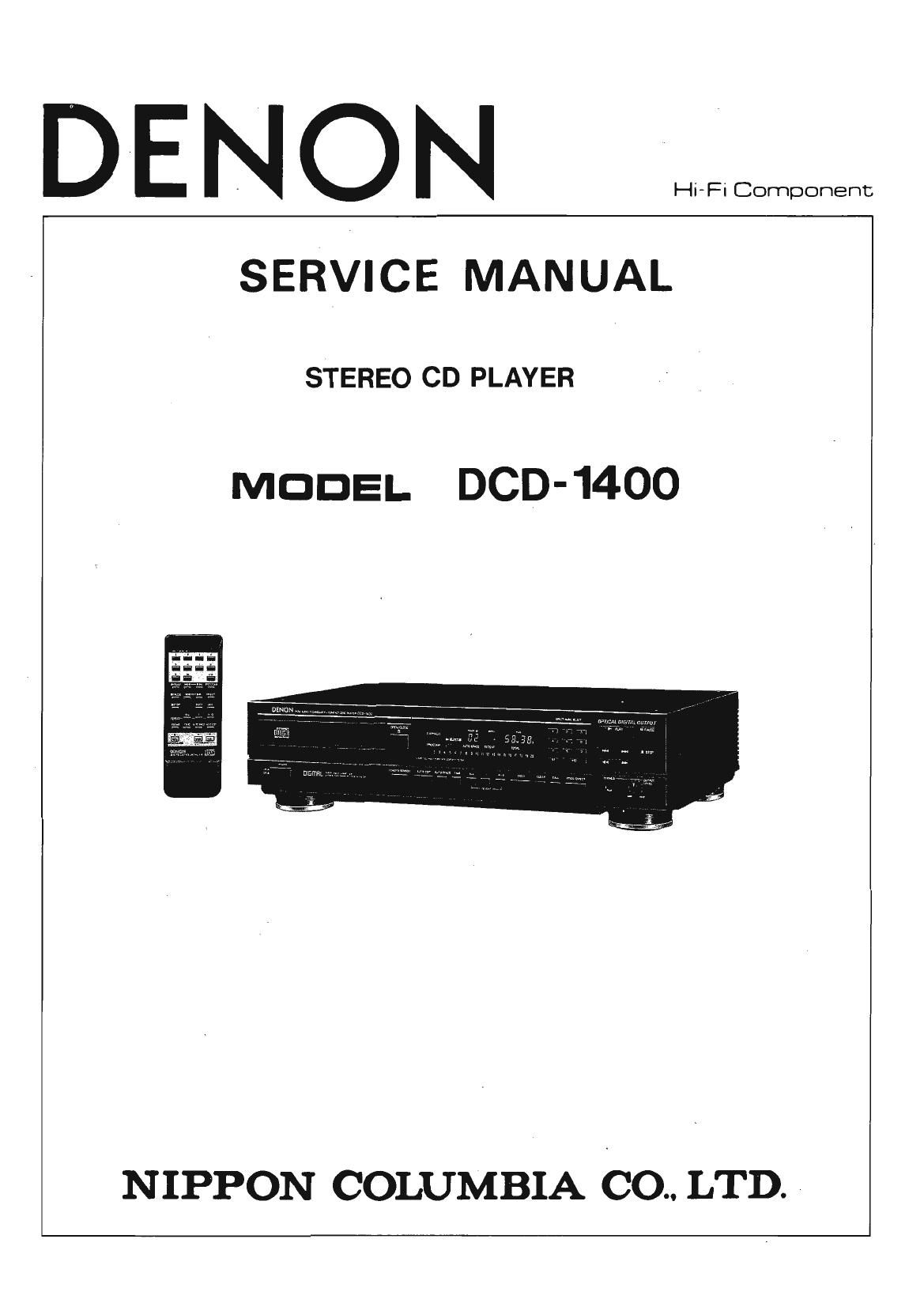
Denon DCD 1400 Service Manual

This is the 38 pages manual for Denon DCD 1400 Service Manual.
Read or download the pdf for free. If you want to contribute, please mail your pdfs to info@audioservicemanuals.com.

Page: 1 / 38
left right
Denon DCD 1400 Service Manual

Extracted text from Denon DCD 1400 Service Manual (Ocr-read)


Page 2

TABLE OF CONTENTS

The DOD-1400 compact laser disc player utilizes a unique DENON

Super Linear Converter which prevents deterioration of sound quality
in the PCM playback system, assuring accurate reproduction of sound
record on compact laser discs, in the studio or in live sound produc-
tion areas. The parts for this high performance disc player have been
selected with careful discrimination. to produce high quality, realistic
playback of the full musical production.

(1)

(2)

Double Super Linear Converter

This unique, DENON converter system prevents the zemocross
distortion that causes deterioration in PCM reproduction quality.
The result is perfect reproduction of concert hall quality.
Built-in High Performance Digital Filter

Independent digital'analog converters are used on the left and
right channels of the DOD-1400, and a high precision digital
filter with quadruple oversampling is used, as well as a built-in
LC-OFC analog filter. These filters make clear reproduction with
good rise possible.

(3)

(4)

(SI

(6)

FEATURES ............................................................ 2
SPECIFICATIONS ....................................................... 3
NAME AND FUNCTIONS OF PARTS ....................................... 4~6
NOTE FOR HANDLING OF LASER PICK-UP .................................. 7 ~ 9
DISASSEMBLY ......................................................... 10
DISASSEMBLY OF MECHANISM UNIT ...................................... 11,12
ASSEMBLY ......................................................... 12, 13
TURNTABLE HEIGHT ADJUSTMENT ......................................... 13
ADJUSTMENT ....................................................... 14 ~20
HEAT RUN MODE FUNCTION ........................................ l ...... 21
IC TERMINAL FUNCTION LIST .......................................... 21 ~ 25
PARTS LIST OF P.W. BOARD ............................................ 26, 27
EXPLODED VIEW ................................. _ ...................... 28
PARTS LIST OF EXPLODED VIEW ........................................... 29
PARTS LIST OF PACKING & ACCESSORIES ..................................... 29
PARTS LIST OF FG-76O MECHA UNIT ......................................... 30
EXPLODED VIEW OF FG-760 MECHA UNIT ..................................... 30
WIRINGDIAGRAM.......................... ............................ 31
P.W. BOARD ........................................................ 32 ~ 34
SCHEMATIC DIAGRAM ................................................... 35
SEMICONDUCTORS ...................................................... 36
FEATURES

Remote control unit with variable volume

In addition to the Play, Pause, Stop and Direct Select function
using the 10 key pad on the remote control unit, it is also possi-
ble to vary the volume with the (+) and (-I keys. The remote
control function greatly improves the ease of use of the 000-

1400 player.

Digital OUT is an optical output device

This device outputs information from a compact disc in digital
form, making it possible to play music with an external digital
processor or Digital-to-Analog unit. In addition to coaxial out-
put, an optical output device is also provided, eliminating the
interference of noise and improving audio quality.

Anti-vibration Consturction

A double top cover, anti-vibration weighted bottom, sintered
alloy insulators has been used to improve the anti-vibration
effects.

8-cm CD software, to be introduced in the future, can be used.
8-cm CDs can be played without the use of an adapter.

Page 11

DISASSEMBLY OF MECHANISM UNIT

o Mechanism Unit (FG-760) Clamper arm
(1) Pull looder frame in ®, _,® @ other, and undo (up position)

base plate hook as per auxiliary figure. Lowery/FM

Hook \gijll Loader frame
Control gear :fi
(Fully turn clockwise) \

(2) Remove 4 special screws, rise it to arrow direction,
and then pull backward.

(Caution) When remove the unit, be sure to take power
cord off. Also, use list ring connected to ground
via 1 Megfl resistor. Never touch laser P.U. if it
is necessary to remove wire from laser P.U. be
sure to shortcircuit (solder bridge) the laser.

0 Slide Shaft

Turn mold part to arrow (D direction with fingers or a
G) screw driver, and pull to arrow @ direction.

<

0 Loader Frame (when loader motor does not turn)
Undo clamper arm hooks in 6), ® order, push it to
arrow ® direction, and undo base plate hook. (refer to
mechanism unit disassembly) : ' Clamper arm


Undo clamper
arm left hook.

Loader frame

11