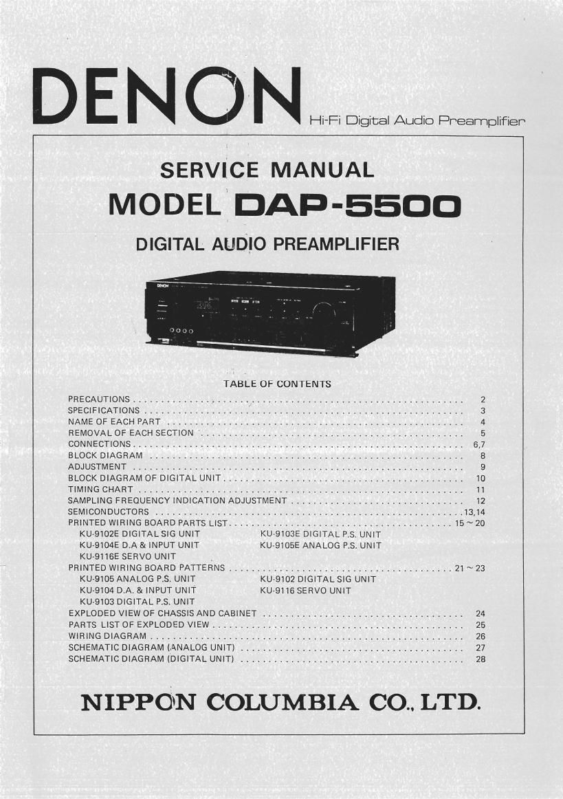
Denon DAP 5500 Service Manual

This is the 26 pages manual for Denon DAP 5500 Service Manual.
Read or download the pdf for free. If you want to contribute, please mail your pdfs to info@audioservicemanuals.com.

Page: 1 / 26
left right
Denon DAP 5500 Service Manual

Extracted text from Denon DAP 5500 Service Manual (Ocr-read)


Page 1

D E N O N I-II-Fi Digital Audio Preamplifieh

SERVICE MANUAL
MODEL, DAD-5500

DIGITAL AUDIO PREAMPLIFIER

TABLE OF CONTENTS

PRECAUTIONS ........................................................... 2
SPECIFICATIONS ......................................................... 3
NAME OF EACH PART ..................................................... 4
REMOVAL OF EACH SECTION ' ............................................... 5
CONNECTIONS ........................................................... 6,7
BLOCK DIAGRAM ........................................................ 8
ADJUSTMENT ........................................................... 9
BLOCK DIAGRAM OF DIGITAL UNIT ........................................... 10
TIMING CHART ......................................................... II
SAMPLING FREQUENCY INDICATION ADJUSTMENT ............................... 12
SEMICONDUCTORS ....................................................... 13,14
PRINTED WIRING BOARD PARTS LIST ........................................ 15~20

KU-9102E DIGITAL SIG UNIT KU-9103E DIGITAL P.S. UNIT

KU-QIO4E D.A & INPUT UNIT KU-QIOSE ANALOG P.S. UNIT

KU-9116E SERVO UNIT ,
PRINTED WIRING BOARD PATTERNS ........................................ 21 ~ 23

KU-9105 ANALOG P.S UNIT KU-9102 DIGITAL SIG UNIT

KU-9104 D.A. & INPUT UNIT KU-9116 SERVO UNIT

KU-9103 DIGITAL P.S. UNIT
EXPLODED VIEW OF CHASSIS AND CABINET .................................... 24
PARTS LIST OF EXPLODED VIEW ............................................. 25
WIRING DIAGRAM ........................................................ 26
SCHEMATIC DIAGRAM (ANALOG UNIT) ........................................ 27
SCHEMATIC DIAGRAM (DIGITAL UNIT) ........................................ 28

NIPPON COLUMBIA 00.. LTD.

Page 2

I DAD-55m: -

Installation Precautions

I

This device (digital audio device) uses a microcomputer tor control of the internal electronic
circuits. In the event that this device is used at the same time as a tuner or television, Inter
terence could occur either in the sound iron: the tuner or the picture on the television.
Please take the following precautions to avoid such occurrences.
- Keep this device as far away from the tuner or television as possible.
a Keep the power cable and other cables connected to this device separated from the antenna

wires of the tuner or television.

o Interference is particularly likely to occur when an indoor antenna or a 300 ohm feeder
line isused, so instead use an outdoor antenna and a 75 ohm coaxial cable for the antenna.

75 ohm coaxial ea in

For USA. and Canada models.

CAUTION

CORgagiség/PgthEEELEggnégszoc; DO NOT usE THIS (POLARIZED) PLUG WITH AN EXTENSION
. L H a UTLET UNLESS THE E ADES CAN 6
PREVENT aLADE EXPOSURE. L E FULLY INSERTED To

For United Kingdom modal only.

WARNING:

As the colours or tha wiret In the mains Ind ol this
appliance may not correspond with t ploured
marklrwt identilying lhl terminals in your pin!
proceed as tollowt:
1-h- win wh a coloured blue must be connected
to the terminal which Is marked with the letter N
or coloured block. Tha wire which is coloured
brown must be connected to the terminat which is
mlrked with the letter L or coloured rad.

IMPORTANT

. . l
The wires in this main! lead are coloured in accord-
, ance with the Iollowin coda:
The tone which it coloured anowu must he a
connected to thl terminll '4"ch I: marked with Elul: Neutral
the letter Lor coloured RED. 1 Live

SPECIFICATIONS

ANALOG SECTION
input terminals

Input sensitivity/Input impedance: LlNE-i-Z, ; 1 W10 kohrn

Output terminals
Rated outputllmpodance:

Maximum output:
Frequency response:

Harmonic distortion:

SIN ratio:

DAC OUT terminals:
Output impodanca:
Output vnluna:

BAP-55cm -

SOURCE DlRECTDN

TAPE-1'2 150 mV/IOkohm SOURCE DIRECT-OFF

LINES :1V/IU kohm lBalanced input) SOURCE DIRECT-0N
150 mV/IO kohm (Balanced input) SOURCE DIRECT-OFF
Suitable input terminals XL tvpe CANNON plugs

PRE-OUT-I : 1 mo ohm

PREOUT-Z (Balanced output) :2 wow ohm

PREDUT-I 15vrms (Unbalanced~tvpe) SDVrms (Balanced-type)
1H1 ~ 300 kHz :g as

0.002% 20 Hz ~ 20 RH! 5 v our

116 dB

Analog output terminals following the D/A converter

470 ohm

2 v (at 10 kohm load. cu max Hoarding level)

NOTE: Specifications are from the regular RCA type unbalanced input/output terminals without specifying Balance-

ed input/output".

DIGITAL SECTION
Digital input/output tynam.
Input terminals
Optical input terminal:
COAXIAL input:
DIGITAL TAPE tnrmlnals:

D-A mnvlrsion mlthod:
Filters:

Frequency response:
SIN ta
Dymmm range:

Total harmonic distortion:
Channol separation:

l
omen FUNCTIONS
Aptomatt twitching nfaamplinq
froquancy:
PRE our switch:

GENERAL
Power wppiy/PWI mnumption:

Dc Output:
Dimlnsion:
Weight:

Digital audio interface format

DIGITALI (1 system)

DIGITAL»? and 3 [2 systems) 0.5 vap7750hm
DIGITALTAPE. MONITOR (1,5 Vpp-750hm
DIGITALTAPE . REC 0.5 Vp-p-75ohm

40A push pulls super linear Convener

4-times oversampling digital filter, C.A.L.P. 7~pole analog filter

2 Hz ~ 20 kHz 20.2 dB

110 dB

More than 97 dB
Less than 0.002% (1 kHlI

More than 100 dB (1 I011)

32 kHz, 44,1 kHz,48 kHz
ON, OFF

120 VAC 60 HZ/25W (for USA, Canada)

220 VAC 50 Hz/ZSW liar Europe)

240 VAC 50 Hz/ZSW (for UK and Australia)

110/120/220/240 VAC 50/60 HdQO W (for Asia ........ multiple)

DC 12 V 1 mA

434 mm (17-3/32") W x133 mm (Eels/64") H x 380 mm (14-61/64") D
13.7 kg (30 lbs 3 01)

Specifications and contents are subject to change without notice for purposes of improvement.

NOTE: The Iollowing coda: correspond to the appropriate models.


E2 for Europe, Eu tor U.S.A., EA for Australia, EK tor u.K:
El Ior Atia and Ec for Canada.
This Service Manual is prepared based on Eu Black Version.