Decca type a compensator instruction

This is the 1 pages manual for decca type a compensator instruction.
Read or download the pdf for free. If you want to contribute, please mail your pdfs to info@audioservicemanuals.com.

Page: 1 / 1
left
decca type a compensator instruction

Extracted text from decca type a compensator instruction (Ocr-read)


Page 1

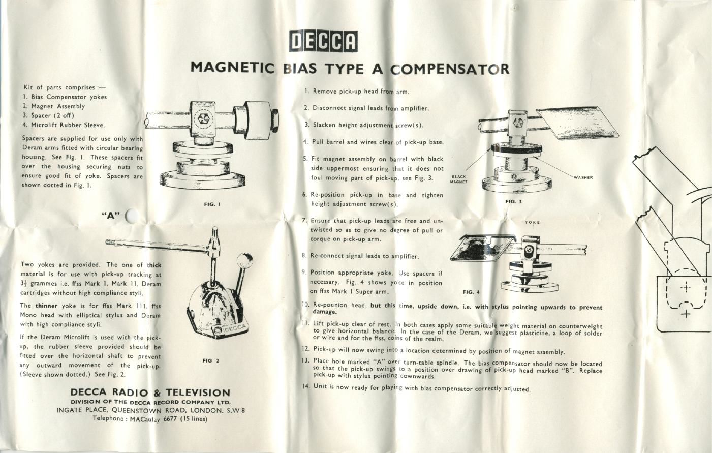
Kit of parts comprises :-
l. Bias Compensator yokes

EEEEE]

MAGNETIC BIAS TYPE A OMPENSATOR

Remove pick-up head I arm.

2. Magnet Assembly 2. Disconnect signal leads! amplifier.
3. Spacer (1 off)
4. Microlift Rubber Sleeve. ' 3. Slacken height adiustme screwls).
SPICWS "9 supplied '0 59 0M) WI 4 Pull barrel and wires clear of pick-up base.
Deram arms fitted with circular bearing
housing. See Fig. I. These spacers fit 5. Fit magnet assembly on ba'rel with black
over the housing securing nuts to side uppermost ensuring thu it does not
ensure good fit of yoke. Spacers are foul moving part of pick-up see Fig. 3. fig; 5
shown dotted in Fig, I.
6. Re-position pick-up in has and tighten
. . FIG. 3
height adjustment screw(s)
7. Ensure that pick-up leads are free and un-
twisted so as to give no degree of pull or
torque on pickup arm.
8 Re-connect signal leads to anplifier.


Two yokes are provided. The one of thick
material is for use with pick-up tracking at
3} grammes Le. fiss Mark I. Mark II. Deram
cartridges without high compliance styli.

The thinner yoke is for Nss Mark H]. I?
Mono head with elliptical stylus and Dt-ram
with high compliance styli.

If the Deram Microlift is used with the pick-
up. the rubber sleeve provided should be
fitted over the horizontal shaft to prevent
any outward movement of the pick-up.
(Sleeve shown dotted.) See Fig. 2.

FIG I

l

I), Re-position head. but this time, upside down

il.

Position appropriate yoke. Jse spacers if
necessary. Fig. 4 shows yoke in position
on ffss Mark | Super arm.

. with ylus pointing upwards to prevent

damage.

Lift pick-up_c|ear of rest. In both cases apply some suitabl weight material on counterweight
to give horizontal balance.~ In the case of the Deram. we 28? plasticine. a loop of solder
or wire and for the I755. toms of the realm.

l2. Pi

I}. Place hole marked A" over turn»table spindle. The bias compemator should now be located

so that the pick-up swings to a position over drawing of pick-up head marked "B". Replace
ple»up with stylus pointing downwards.

H. Unit is now ready for playing with bias compensator correctly adlusted.

DECCA RADIO 81 TELEVISION
DIVISION OF THE DECCA comb COMPANY LTD.
INGATE PLACE. QUEENSTOWN ROAD. LONDON. S.W8
Telephone: MACaulay 6677 ('5 lines)