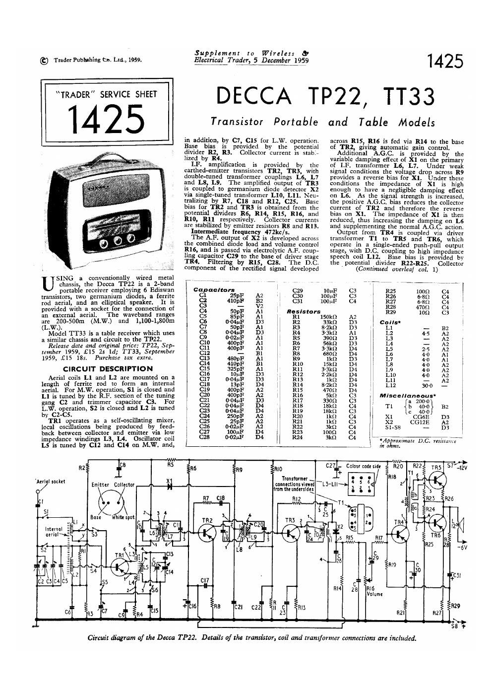
Decca tt 33 service manual

This is the 2 pages manual for decca tt 33 service manual.
Read or download the pdf for free. If you want to contribute, please mail your pdfs to info@audioservicemanuals.com.

Page: 1 / 2
left right
decca tt 33 service manual

Extracted text from decca tt 33 service manual (Ocr-read)


Page 1

(9 Trader Pubhahing to. Ltd., 1959.

TRADER" SERVICE SHEET

1425

SING a conventionally vvired metal
I I chassis, the Decca TP22 is a Z-bafld
portable receiver employing 6 Ediswan
rod aerial, and an elliptical speaker.

an external aerial.

are ZOO-SOOm (M.W.)

1959, £15 185.

aerial.
gang C2 and trimmer capacitor C3.

by czvcs.

impedance windings L3, L4.

Supplament to Wireless 0
lingual Tradflé Decembeu9§9

DECCA T

Portable

in addition, by C7, C15 for L.W. operation.
Base bias is provided by the potential
divider R2, R3. Collector current is stable
lized by R4.

LF. amplification is provided by the
earthed-emitter transistors TRZ, TR3, with
double-tuned transformer couplings L6, L7
and 1.8, L9. The amplified output of TR3
is coupled to germanium diode detector X2
via single-tuned transformer L10, L11. Neu-
tralizing by R7, C18 and R12, C25. Base
bias for TRZ and TR5 is obtained from the
potential dividers R6, R14, R15, R16, and
R10, R11 respectively. Collector currents
are stabilized by emitter resistors R8 and R13.

Intermediate {requency 472kc/s.

The A.F. output of X2 is developed across
the combined diode load and volume control
R16, and is passed via electrolytic A.F. coup-
ling capacitor 629 to the base of driver stage
TRO. Filtering by R15, C28. The DC.
component of the rectified signal developed

l7 WW " W l:

Transistor

1425
P22, TT33

and Table Models

across R15, R16 is fed via R14 to the base
of TRZ, giving automatic gain control.
Additional A.G.C. is provided by the
variable damping client of X1 on the primary
of 1.F. transformer L6, L7. Under weak
signal conditions the voltage drop across R9
provides a reverse bias for X1. Under these
conditions the impedance of X1 is high
enough to have a negligible damping efiect
on L6. As the signal strength is increased,
the positive A.G.C. bias reduces the collecmr
current of TRZ and therefore the reverse
bias on X1. The impedance of X1 is then
reduced, thus increasing the damping on L6
and supplementing the normal A.GtC. action.
Output from TR4 is coupled via driver
transformer T1 to TRS and TRS, which
operate in a single-ended push-pull output
stage, with DC. coupling to high impedance
speech coil L12. Base bias is provided by
the potential divider RZZ-RZS. Collector
' (Continued overleaf col. 1)

cal


F M 3;: is: C3 is: 22
. t . . 1 2 6-8
transistors, two germanium diodes, a felrtriti: g 410;]: 32 1 C31 100:]: C4 ' 5%; 67-88 82 l
provided with a socket for the connection of C4 Mia-F X? 3 Reslstors R29 4189 C3
The wavcband ranges as SSpF Al R1 1 om a2
and 1,100-1,800m g? 015M; 23 fig 833:3 B; ciillen B2
L.\V.). 0p 1 . l _
s C8 O-MuF D3 R4 3'3) Al L2 4-5 A2
Model TT33_ is a table receiver wlliiglzi uses C9 002: A1 R5 3909 D3 L3 __ A2
a similar chasSis and circuit to. the T . C10 400pF A1 R6 561:!) D3 L 4 _ A2
Release date and 31" 1m? 22: 531" C11 400pF Al R7 33m D4 L5 2.5 A2
tembev 1959, £15 2: 1d; TT33, September C12 - Bl Rs 63052 D4 L6 4-0 A1 l
Pm 2 8:: age; a so its 32 1:; 3-3 s l
p -
CIRCUIT 0556mm" a: 25 s; l at 32 a, :2 2; l
Aerial coils L1 and L2 are mounted on a C17 0.04"]: D3 ll R13 1kg D4 L _ A2
length of ferrite rod to form an internal C18 13pF D4 1 R14 Saki) D4 L12 3vo -
For M-W- WW5 t we and a: 233»: i: t a: 422:: 2; WWW
L1 is tuned by the R.F. section of the tunlgrég 8%; 0.041311: 82 1 g}; 338 E: r T1 {3 223%} M
. . - 004 '
LW. operation, 52 is closed and L2 is tuned 023 0.04:]:- D4 | 11%: fig 8: x; C5233 D3
. l r C24 250pF A2 1 3
TR! operates as a self-osuflaung mixer, 625 25px: A2 R21 ikn C3 xz CG12E n2
local oscillations being produced by feed- 026 0021.1? A2 R22 3k!) C4 l Si~§8 - D3
back between collector and emitter via loyv C27 100141? B: fig 1328 g 7 , ,
Oscillator coil 623 0'02: prpmxmmre D. . urinal:
L5 is tuned by C12 and C14 on M.Wt and, m ohm.
. _ ~ g ' $7 _
N2; f8 RS ins : R9 - RIO (2&4, Calour code shit R20 1R5 12v
lrunslnnncr ' '/ RIS
x . . ~ _ 4 s t
' canntctmnsmwtd L5 Ll|~> ti
Emitter Collector _.i.__ Irnmtheundmidg 3 a 1.
RIZ
I I
1.
2.
NW
C
c 3 29
I2 -
CM
i
R16
6 28 Volume
l5


Circuit diagram of the Decca TP22. Details of the transistor, coil and transformer connection: are included.

Page 2

DECCA
TP22

142

gage: socket
Circuit Description-

currents are stabilized by R26 and R27.
Negative feedback is applied from L12 to
the base of TIM via R28,- C31, R29 and
R19.

CIRCUIT ALIGNMENT

Equipment Required-A signal generator,
modulated 30 per cent at 400c/s and an A.C,
voltmeter for use as output meter.
1.-Switch the receiver to M.Wi Turn the

volume control to maximum and set the

tuning gang to maximum capacitance. Con-
nect the output meter across the speaker
speech coil L12. Connect. the signal gen-
erator live lead to the tapping on L1 (loca-
tion reference 32). and its earthy lead to

the junction of R3, C6. .
Z.-Feed in is modulated 472kc/s signal and

adjust the cores of Ll0 (A2), L9 (D4), L8

(A2), L7 (D4) and L6 (All for maximum

output, progressively reducmg the signal

generator output as the Circuits come Into

:-

3.--Checlt that with the tuning gang at
maximum capacitance the cursor _comcides
with the datum marks at the right-hand
ends of the tuning scales.

Iii-Loosely couple the signal generator out-
put to the lerrite aerial rod. Tune the re
ceiver to 600kc/t. Feed in is modulated
600kc/s signal and adjust the core of L5
(location reIerence A2) for manmum out-

at

5.3Tune the receiver to 1,500kc/s. Feed
in a modulated 1,500kc/a signal and adtust
C12 and C3 (location references Bl, Bl)
for maximum output.

6.-Tune the receiver to GOOkC/s. Feed in
a sootwé. signal and slide_L1 (location rel:-
erence 2) along the ferrite rod for main-
mum output. If considerable adtustment
of Ll is required repeat operations 4, S
and 6.

7,-Switch the receiver to LW. and tune it
to ZSOkc/s. Feed in a modulated ZSOkc/s

Supplement V to Wirelerr 5'
Electrical, ,TKMLEJRr-ezzflzétfifl

signal and adiust C7 and C4 (location ref--
erence Al) for maximum output. As oscil-
lator pulling may occur when adiusting C7,
care should be taken to adjust C7 and C4
at the correct tracking point.

Si-Tune the receiver to l70kc/s. Feed in
is modulated l70kc/s signal and slide L2
(location reference A2) along the ferrite
rod for maximum output. Repeat opera-
tion 7 if considerable adjustment of L2 is
required.

GENERAL NOTES

Swirehee-Sl, 53 and SS close on M.W.;
52, S4 and S6 close on L.W.

.Transietors.-Replacement transistors. are
supplied by the manufacturers' spares depart-
ment in two padtages which are identified
as type R.F.l and type L.F.l. The R.F.l
package contains one M102 and two XAlOl
transistors; the LEI package contains one
XBIOB and a matched pair of XClOl tran-
SlStOl'Sl

The manufacturers recommend that if a
fault develops in one of the R.F./I.F. tran-
sistors TR] TR: or T113, all three should
be replaced. Similarly, should it become
necessary to replace one of the AF. tran-
sistors TIM, TRS or T116, all three should
be replaced.

Warning-Transistor: may be perma-
nently damaged if the full negative voltage is
connected to their bases, or if continuity
measurements are made with the transistors
in circuit. They may also be damaged by

Right: Undemde
view of the chassis

Below: Diagram. of
the tuning drwc
system.

___---§.J-®

1* turns round
control spindlt Q

Cursor

V Left: Plan view
of the chassis.

Right: Diagram

of the switch unit

81-58 as seen in
location D3.

the application of excessive heat. it a tran<
sistor has to be removed or replaced, the
soldering or unsoldering operation should be
comlpleted as quickly as possible using on
cart ed soldering iron. A heat shunt, such
as a pair of pliers, should be clamped across
the transistor lead between the transistor and
the soldering iron during the soldering or
unsoldering of its leads. Take care to avoid
scratching the paint on glass-cased tran-
sisters.

Drive Cord Replacement-About 38in of
nylon~braidcd glass yarn is required for a
new drive cord. It should be run as indi-
cated in the sketch in cols. l, 2, where it is
drawn as seen when viewed from the front
of the chassis with the tuning scale and
backing plate removed and with the gang at
minimum capacitance.

Batteries.-The batteries recommended by
the manufacturers are two Ever Ready Lan-
tern type 996s, rated at 6V each, connected
in series.

Transistor Analysis

Collector current readings given in the tnble
pelcw are those derived from the manutscmrerr'
information. They were measured on a high-
resistance meter, the positive terminal being
connected to the collector in each case. Theme
of a meter with an internal resistance lower than
10,000fl/V can give rise [0 misleadin readings.
The receiver must be switched or? hefore un-
soldering the collector lead and connecting the
millimeter in circuit. See Warning" under
General Notes," Do]. 2.

Primed in England by Cmntall Pun

Ltd., Paris Olden. Landon. $1.1.