Decca tpw 70 service manual

This is the 2 pages manual for decca tpw 70 service manual.
Read or download the pdf for free. If you want to contribute, please mail your pdfs to info@audioservicemanuals.com.

Page: 1 / 2
left right
decca tpw 70 service manual

Extracted text from decca tpw 70 service manual (Ocr-read)


Page 1

© llifle Electrical Publications Ltd" I962

TRADER SERVICE SHEET

linuili-IQ

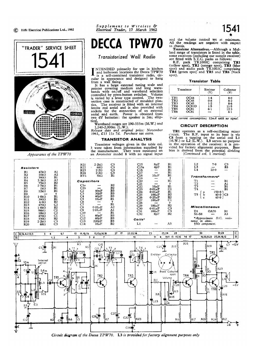
Appearance of the TPW70

Supplement to Wireless 57
Electrical Trader, 17 March 12672

DECCA TPW70

Transistorized Wall Radio

NTENDED primarily for use in kitchen
I and bathroom locations the Decca TPW70

is a self-contained transistor radio, cir-
cular in appearance and designed to hang
from a wall fixing.

It has a large external tutung scale and
pointer covering medium and long wavea
bands with on/oif and waveband selection
controlled by press-button switches. Volume
i5 varied by a lever type control. The two-
section case is constructed of moulded plas-
tics. The receiver is fitted with an internal
ferrite rod aerial and is also rovided With
sockets for the connection 0 an external
aerial and earth. Power is obtained from
two 6V batteries: the speaker is Sin; ellip-
tical.

Waveband ranges are 190-555m (M.W.) and

l,140-2,000m (L.W.).

Release date and original price: November
1961, £13 11: 74. Purchase tax extra.

TRANSISTOR ANALYSIS

Transistor voltages given in the table col.
3 were taken from information supplied by
the manufacturer. They were measured on
an Avometer model 8 with no signal input

15941

and the volume control set at minimum.
All the readings are negative with' respect
to chassis.

Transistor Alternatives.-Although a Mul-
lard range of transistors is listed in the mhle,
some receivers (including our sample receiver)
are fitted with S.T.C. acks as follows:

R.F. pack TKIOOSC comprising TR]
(yellow spot), TRZ (orange spot), TR3 (blue
spot) and audio pack TKIOOZC comprising
TRIS (green spot) and TRS and TR6 (black
spot .

Transistor Table

Transistor Emitter Collector

4 (V) (V)
TRl OC44 14 so
TM 0015 11-3 8-2

1 T113 0015 12 86

TR4 0(2le 15 11s

1 TRS ocsl 6~l 23
TR6 0C81 -- 5-1

Tu'iZzl'Efm: consimpn'an; mm with m7 5.11m"
CIRCUIT DESCRIPTION

_TR1 operates as a self-oscillating mixer
c-reuit. The RP. input to its base is via
C8 from 3 ts ping on the aerial coil Ll
(MAM) or L2 L.W.). L3 serves no purpose
in the operation of the receiver: it is pro-
vlded. for factory alignment purposes. Base
bias is denved from the potential dividing
(Continued col. 1 avevleuf)

internal
aerial


Emitter

Collette!


! R21 22m <33 C15 ape 131 L2 7-0 (:3
Resistors { iii; 2633 8; gig 41:1: 31 13 50 m
E; fig 2; R24 2-211 cs C17 - Bl
R3 39015 El RV 5m 31 ' 8:3 1011 B; Transformers
R4 33 AZ capacitors C20 - 131 T1 - 131
R5 75m 32 021 _ 1. T2 __ M
R6 a71:12 Bl Cla - 132 (222 10 r: 31 T3 Bl
7 9 m 3 - 32 C23 o~otui= c1 T4 - 81
R8 12m B1 C2 40pF 133 w 0,0111? Bl 15
R9 - + C3 301:1: 133 3
R10 1-st 131 Q, P 113 C25 room 132 T5 b 400 c3
R11 39011 B! C5 10»? 131 C25 0'25" 32 ° 400
R12 5-39 132 Cs - + 8%; 10011: Cf
R13 4701: c2 c7 - El (:29 100 F 32
RH 1-8kfl B2 C8 0051117 A2 , " Mlscellanaous
R15 56m c2 C9 o-omF Al 2;? 018(1); g; D1 0.1170 B1
R16 lBkll c2 C10 - Bl
R17 4700 c1 (:11 mm 133 C32 Sp}: 32 515 A3
R18 3300 112 C12 40pF as eons. Approximate 0.0. ms.
R19 Z-an c3 C13 220;»: 133 . tune: in ohms.
R20 660 Cs C14 101}: 132 i 1 L1 - A3 +Na component.
C u,1fl,4,2,l2,§ 5 8 9.7 I! 11,10, 1515436, 17 17 22,20,1 23 25,24 26 30 3,2° C
a 1,2 4 s s 15 1 1o 11 a nv1 13 15,16 14 11 mum 25.24;: 9
WW .9
' % C25" 1115I W4 " 57 "2V
C5+ H' + +c31

-4

at,

1" (222+

C27

cle
+ -517
\

\

6.4.}:

Circuit diagram of the Decca TP W70. L3 is provided for factory alignment purpose: only

Page 2

DECCA
TPW7O

1541

L.W. MW Off


O 5 i

use i
LI
WWWilllllllnlllllllllllllUll

I
_L.

Circuit: Description-continued
network R1, R2. T2 is tuned at oscillator
frequency in conjunction with Clb and C11
(M.W.) with C12 and C13 switched in paral~
lel (L.W.). Oscillator voltage is injected in
T11] emitter and T2 coupling windings pro-
vide feedback from collector to emitter.
The resultant intermediate frequency
selected by double-tuned transformer T1 in
TRl collector circuit is at 472 Kc/s, This
is amplified by lst and 2nd I.F. flmpllr
tiers TR2 and T113, which are coupled by

S4

334 57 564 EMU @50ng
/

V Ni ['53an IMSSLI n J

Prat-button switch Unitas seen from the same
directian at the arrow in lacatmn reference
A3 in the chassis illustration (abate)

valid? '

Supplement to Wireless {9'
Electrt'iaLTrader, 17 March 1962

Component-side view of the printed circuit panel

Jud-{r

tuned transformer T3, and is then applied
via T4 to the detector diode D1. C15, ClSa
and R6 comprise a neutralizing network for
TRZ internal capacitance. D1 operates with
slight forward bias derived from the potential
dividing network R5, R8, RVl and R12 which
improves its sensitivity at low signal levels.

The rectified audio output is filtered by
R11 and C24 and developed across the
volume control and load resistor RV]. The
rectified carrier current produces a positive
D.C. potential across RVl, R12 which is
fed back to the base of TRZ as A.G.C. bias.
TR4 operates as audio driver stage whose
output is coupled via T5 to the bases of
TRS and TR6 in anti-phase.

CIRCUIT ALIGNMENT

Equipment Requirevan A.MV signal
generator; an AC voltmeter; a lkl! resistor
and a bladed type insulated trimming tool.
1.~Switch to M.W. and set the tuning gang

to the fully meshed position. Connect the

signal generator across M.W. aerial coil

Ll: connect the A.C. voltmeter across the

speaker speech coil L4.
2.-Feed in a 472kc/s modulated signal and

maintaining the input only sufficiently high
to give a reasonable deflection in the output
meter, adiust the top and bottom cores of

T1 and T3 and the core of T4 for maxi-

mum output.
3.-Repeat operation 2.

Connect the signal generator via the lkfl


a-T-
C30QTL2 cal I
Dias [U]
lfl ..

I
J-

resistor to the external aerial socket. Tune
receiver to 460m. Feed in a 652kc/s signal
and adpust T2 and L1 for maximum output.
Adjust Ll by sliding its former along the
ferrite rod.

S.-~Tune receiver to Z30m. Feed in a
1.300kc/s signal and adjust C11 and C2
for maximum output.

6 -Repeat operations 4 and 5.

7.-Switch to LW. and tune receiver to
1,750m. Feed in a 170kc/s signal and
admin C12 and L2 for maximum output.
Note: When adjusting C12 there may be
a degree of oscillator pulling. Care should
be taken to adjust C12 and L2 for maxi-
mum signal at the correct tracking point.

8.~Tune receiver to 1,250m, Feed in a
240kc/s signal and adjust C4 for maximum
output.

9.-Repeat operations 7 and 8.

GENERAL NOTES

Dismantling-To remove the chassis from
the case first remove the case rear by taking
out three self-tapping screws.

Remove batteries.

Pull oi? the tuning knob and take out two
hexagon headed screws thus revealed securing
the tuning pointer and volume control lever,

Remove two spring Clips securing the
chassis to the case front, unplug the speaker
connections and withdraw the chassis.

Battery.-Two Vidorcnax T6001 or Ever
Ready PPl 6V.

Printed :71 Great Britain In Cam-mu Press, Ltd.. rum Garden, Siam/0rd Slit-:21, Landau, 5.5.1, and Published by Ilifle Electrical Publications, Ltd.

Durst-t Home. Stamfoni Street. Landml. S.E.1.