Decca tp 90 a service manual

This is the 4 pages manual for decca tp 90 a service manual.
Read or download the pdf for free. If you want to contribute, please mail your pdfs to info@audioservicemanuals.com.

Page: 1 / 4
left right
decca tp 90 a service manual

Extracted text from decca tp 90 a service manual (Ocr-read)


Page 1

O Ilifie Technicll Publications Ltd.. 1967

TRADER" SERVICE SHEET

1825

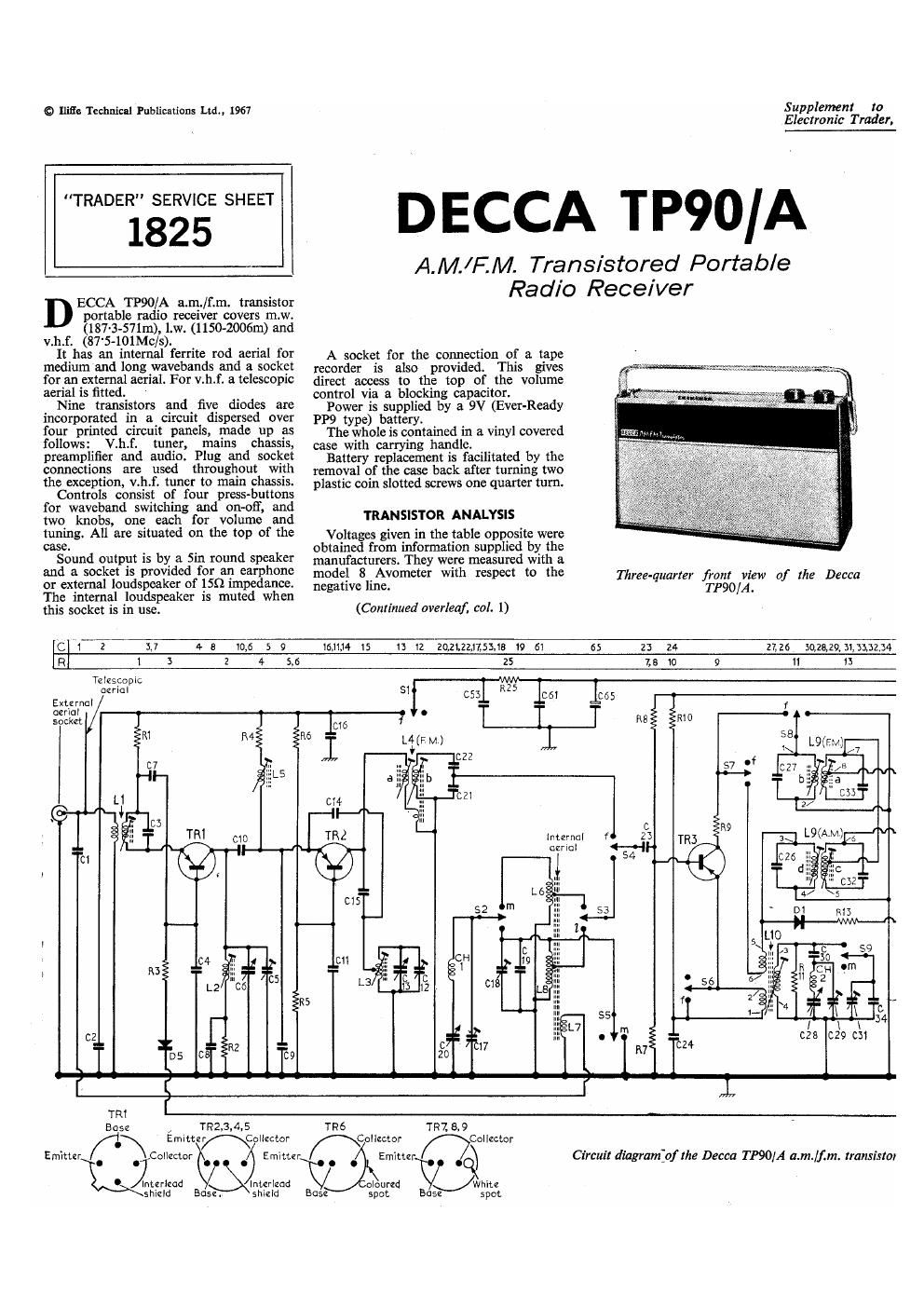
ECCA TP90/A a.m./f.m. transistor
portable radio receiver covers m.w.
(13376-571111), LW. (1150-2006111) and

v.h.f. (87'5-101Mc/s).

It has an internal ferrite rod aerial for
medium and long wavebands and a socket
for an external aerial. For v.h.f. a telescopic
aerial is fitted.

Nine transistors and five diodes are
incorporated in a circuit dispersed over
four printed circuit panels, made up as
follows: V.h.f. tuner, mains chassis,
preamplifier and audio. Plug and socket
connections are used throughout with
the exception, v.h.f. timer to main chassis.

Controls consist of four press-buttons
for waveband switching and on-off, and
two knobs, one each for volume and
tuning. All are situated on the top of the
case.

Sound output is by a Sin round speaker
and a socket is provided for an earphone
or external loudspeaker of 1552 impedance.
The internal loudspeaker is muted when
this socket is in use.

Supplement to
Electronic Trader.

DECCA TP90/A

A.M./F.M. Transistored Portable
Radio Receiver

A socket for the connection of a tape
recorder is also provided. This gives
direct access to the top of the volume
control via a blocking capacitor.

Power is supplied by 2. 9V (Ever-Ready
PP9 type) battery.

The whole is contained in a vinyl covered
case with carrying handle.

Battery replacement is facilitated by the
removal of the case back after turning two
plastic 00in slotted screws one quarter turn.

TRANSISTOR ANALYSIS

Voltages given in the table opposite were
obtained from information supplied by the
manufacturers. They were measured with a
model 8 Avometer with respect to the
negative line.

Three-quarter front view of the Decca
TP90/A.

(Continued overleaf, col. 1)

C "1 2 347 4 a "1,5 5 9 16,11,14 IS 1: t2 zqztzmsms 19 51 65 23 24 27.26 so,2e,29,31,3112,34
R 1 5 2 4 5.6 25 7,3 0 9 11 13
Telescopic xii
aerial S] R 5 l i
Ext-mm l 653 I: 061 C65
aerial o 1
socket lcté t RS 10
R6
l v
I-
C l l f 203
Memo 1
ceriol HF TRS
01 54 ._r
l
l
1
c2 " _
- m I'cu

I'

TRl
Bust: /

TR2,3,4.S

fl\ Emltteflollzctor
E . ,,
mutter . ' Collector .' .j Emit.

mterlwd b
shizld Bose.

Interleod
Shield

mollcctor
MEmmzr .j
o urzd Whte
Bose I

TRé 7R7. 8.9

mcmlzctor

Circuit diagrampfthe Decca TP90/A a.m./f2m. transistor

lo
Base 5 pet spot

Page 2

Electrical and


, 13 October 1967 DECCA 1825
-.- TP90A
Iiulslan R39 lskn E3 (:25 0'111F B1 (:64 0 022111? In L8 _ A1
11.1 53011 F4 R40 Mm 133 C26 560pF C2 C55 500113 32 L9 _ (:2
R2 10011 F4 R41 1000 D3 C27 1sopF c2 C66 02211F 31 1.10 - 31
R3 1m F4 342 47m 153 023 2381211 F4 057 o-111F 33 L11 _ 32
34 am 124 34: 2-230 D3 (:29 sopF 31 C68 mm 53 1.12 _ 32
35 mm F4 R44 1000 D3 C30 186pF 31 C69 mm 35 L13 _ 133
R6 10m F4 R45 2-2sz D3 C31 30pF 31 C70 10ch E3 L14 1552 1
R7 3339 C1 R46 1000 D3 C32 5503!? (:2 C71 10ch E3 CH1 ~ C1
35 581m 31 347 2-2:) 1:13 C33 ISOpF C2 C72 500111: 33 CH2 _ c2
39 2200 C1 3411 2-29 D3 C34 150pF 31 C73 soouF 31
51127015 1 151213 11 512 1'1; 51 81: 51811: 51
1 - 14
R12 2-2112 C2 C37 1031' 32 _ "Indians:
R13 6800 El _ C38 1,500pF 32 Calls and Transform": D1 - 32
R14 55m B2 Cancun": (339 0-1111? 32 L1 .- F4 D2 - 32
315 3-314: 32 c1 SSpF 31 010 30051: 31 L2 _ F4 D3 132
R16 330:1 32 C2 o-o1uF F4 C41 11101511 31 L3 3 F4 D4 32
317 47012 32 c3 47pF F4 C42 1,000pF 32 L4 _ F4 D5 - C:
313 15351 32 c4 1,000pF F4 C43 mm 32 L5 3 F4 51.511 - 31
R19 3-31.12 32 C5 20pF F4 C44 Maw 32 L6 _ 31
320 101.11 32 05 - F4 C45 1aopF 32 L7 _ A] 1 Lemma,
321 2-23.11 32 C7 1,000pF F4 C46 0-111F 32
322 22012 32 cs 1,000pF F4 C47 0~luF 32
111 05 11 31 5:2»; 1: 513 111111 11 T
47 1 . u .
1125 4711 31 C11 1,1300%}1 F4 C50 300pF 32 "9" "b"
R26 39012 32 C12 20p F4 C51 250pF 32
R27 680E} B2 013 _. F4 052 0111117 B7. Transistor Emitter Base Collector
325 2211 32 C14 s-zpF F4 C53 0-1111? 31 v) (v) (V)
329 5514) 31 C15 5pr F4 cs4 50pF 32
R30 2214151 32 C16 0-111F C1 C55 o-muF 32 7'31 AF130 5-2 4-5 0-1
331 5st 32 C17 aopF 31 C55 1.00011F 32 T32 AFllS 3-0 2.5 ._
332 22m 32 C18 301517 31 cs7 0-0211F 32 TR3 AF! 45 4.0 0.1 1
353 11:12 31 C19 35pF 31 C55 lOuF 32 T34 AF114 5-0 5.5 1.5
334 180m E3 020 2381217 F4 059 1,000pF 32 TRS AF114 5-9 5-5 05
R35 10m E3 C21 1,000pF F4 C60 04221117 31 TR6 0C71 7-3 5-7 0-3
1155 3-911} 33 022 300;: F4 C61 13-11117 31 TR7 0081/1) 7-7 7-3 1-2
R37 1111 33 C23 o-o1uF C1 C52 o-oamF 32 TRS ocs1 4-5 4-2 0
R38 551:: 153 C24 o-OZuF 31 C63 1,000pF 32 TR9 01:51 9-0 5-9 4-5
2236311353541404243 45,45,44,473741149,5<151,52 5554555957 5554535550 52,57 55 7o 59 71 72 75 74 75 c
1415 12 1111715 20 21 25,2224 211,25 19,27,v111,33,29 50,5132 VRZ 5554 3735,5559 40,42 4145,4544, 48,47 R
' W
Ci l, 4151: 5
7o C72 C73
1123 511133ng R R R R g
f dosedon EM/VHF. 35 37 $39 40% $11-16 3
7, c105:- on 1. w
m =C|osed on MW.
p
L14
.
£11 0 c TR6
57 68
= I-
R TR7
32 559
C75 0
1
VR2
S10 Vo1umz
Earp/hone
11 C71 and ExLLS
334 R36: 8
11
14 35". 38 111J-iccx £10 30 T052 5
42 4 .45 -
. In \-->
EFL-r ~91
C l urcode Colourcodz Colourcode
L10 AM L9 12M, (Siam AM L11 PM wow AVM. L12 EM. 31112
[3° °: 12? g" -219? 52:11
'ed radio receiver. Coiourcodz : 1 1
Bme/VeHow 4 a 1 2 1 4 3 1 2 1 4 5 12 1
030: o 010 o 0 0:0 0 o 010 o

VIEWED FROM UNDERSKDE OF BASES