Decca deccalain service manual

This is the 2 pages manual for decca deccalain service manual.
Read or download the pdf for free. If you want to contribute, please mail your pdfs to info@audioservicemanuals.com.

Page: 1 / 2
left right
decca deccalain service manual

Extracted text from decca deccalain service manual (Ocr-read)


Page 1

DECCA
DECCALIAN

magnet loudxpt'aktr

rrpzmabtr tap/third .rzylur.

Brixtun R/md, Lmrdtm, SW9.

to a beam telrotlt: output valve V2.

speaker.

rectifier V3.
Circuit.

screened

-115
M a? CD
. MTI
MTI 200'
NE TONE
1:) 1'11 1.7 L513 2" © 5411::
LIO
(9% [a 12
1
I1222 c7 220_ 2:8 :31
FWIC C" To GRAM MOTOR 230 2 9
1: AND AMPLIFIER L6 RI :1
R. 10 PICK up 1V mg) 5 _J ON 01:1: swn'cn PICK up
VOLUME MAINS LEAD voLUME

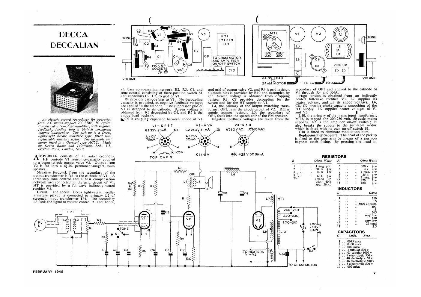
riu bass compensating network R2, R3, Cl, and
tone control consisting of thrccpovslition switch SI
and capacitors C2, C3, to grid ofV

R6 provides cathode bias to V1 lNo decoupling
capacity is provided as negative feedback voltages
are applied to the cathode.
V1 is strapped to its cathode. Screen voltage is
obtained from R7 decoupled by C4, and R5 is the
anode load resistor

Thc suppressor grid at

GRAM TMOIORJ"a TO L4JOL5J

and grid of output valve V2, and R9 is grid resistor.
Cathode bias is provided by R10 and decoupled by
C7. Screen voltage is obtained from dropping
resistor R8. C8 provides decoupling {or the
screen and for the HT supply to VI.

L4, the primary of the output matching trans-
former OP]. is in the anode circuit of V2. R11 is
anode stopper resistor L5 the secondary of
OP], feeds into the speech coil'of the PM speaker.


secondary of OP] and applied to the cathode of
V] through R4 and R4A.

High tension is obtained from an indirectly
heated full-wave rectifier V3. L7 supplies its
heater voltage and L8 its anode voltages. L6,
C8 C9 provide choke-capacity smoothing of the
H1: supply. L9 supplies heater voltages of V1
an V2.

L10, the primary of the mains input transformer,

.111 pin-Mr mind rzprudum fnr uprmimn LC5 5 coupling capacitor between anode of V1 Negative feedback voltages are taken from the MT], is tapped tor 200-250 volt, 50»cycle mains
from AC main: pp/m 200- 250V 50 (yr/rs supplies $2 is the amplifier on off switch; it
Consist: 0/ :1 two stage amplifier, with negative VI - E F 3 7 V2- 6 V 9 V3-5 2 4 also breaks the supply to the turntable motor
fledbmk Milling imu a 674ml: permanent 6235v25mA :1 2 250v4 1111A A'seovAt; A'360VAG which is fitted with its own on- air switch 53.

The pitk up 1.1 a Dtllli C10 is fitted to eliminate modulation hum.
lightweight "mile armature type, fined wit/I 140v A375V Replacement of Sapphire The head ofthe pickup
The turntable (Hill 75mA 50mA is fixed to the tone arm by means of a push- on
mnmr 161111111 (1 Garrard typt- AC7C. li1at/i' bayonet catch fitting By pressing the head in
by Dorm Radio and Television, L111, 1-3, 11 H @\H
M .1-1. Kl-75V
MPLirnziz consists of an anri~microphomc Top CAP G. K '4 5V 5" 55" Ras1sTons
HE pentode V1 resistimcevcapacity coupled R 011 W R aim
> Output 1mm ##2 _-__flatir
V2 rs fed into a 6f-in. permanent-magnet loudr R5 1 .. lrneg.poi. 5 .1 .. 300k iw
- 2 .. 50th {w 6 . ..

Negative feedback mm the secondary or the I W0 3 .. . 80k w 7 .1 1.1.51; $1.1
output transformer 15 fed to the cathode of VI A OPI L6 4 } 60k {w 8 25 k W
ihrec- step tone control and a bass compensation 4 (mad F 13 £73: i
network are connected in the grid circuit of V1. 124 L4 L5 W m" 11 100 it;
HT is provided by a full- -wavc indircctly- heated t R5 R7 and 20

R4 LII INDUCTORS
The specia' Decca lightweight needle- (:9 L Ohms
armature pickup 15 connected to primary L2 of __
input transformer [PI The secondary RII MT] 1 ., 210
L3 feeds the signal to volume control R1 and thence, 2 H 5
3 .. 5000 approx.
-|-l Q 4°?
4 - .
c5 2 o 250 g 365
- -» 220-23 1 very low
L v2 0 3 i150
- _ very ow
20° 2'0 zoo 10 .. ., 261111111
53 £501, 11 1. 25
L10 7" CAPACITORS
n9
1
§
ca 07 ~- 4 .1 tubularSDOv
_ ii: to HEATERS L9 52 s . 1011111111111 1000
'- Vl-VB mo 6 . iieiamolyr 500;
R10 7 .. 4o cloctrol
I g ,, 1136 lelecxriflyucs§§0V
. . eectro ytlc V
, . To GRAM MOTOR 10 .. .002 mm

FEBRUARY 1948

Page 2

DECCALIAN-Continued

and giving an eighth turn anti-clockwise the head
can be removed. Unfastcn the two screws on the
top side of the head. The lower hinged plate of the
assembly containing bar magnets, coil and specially
designed rubbersuspcndcd armature with sapphire
attached, can now be opened out.

Remove rubber moulding and sapphire and
insert new one. (Red spot to rear of recess.) Care
should be taken when fitting new sapphire assembly
to'see that point of needle passes through the
original hole in the plastic seal on tlte underneath
side of head. >

Removal of Motorboard. Before attempting to
dismantle the equipment it is advisable to remove
the bayonet catch plug in pickup head, and to
secure the tone arm to its rest by means of a piece
of wire or string. .

Unscrew the two bolts at the ends of the sloping
panel nearest to the hinges of the lid, and remove
the panel.

Unscrew and remove the four wood screws
holding the motor board in supporting runners at
sides of cabinet. Grip back edge of motor board
firmly and lift and slide it about an inch backwards.
The motor board can now be tilted backwardsso
that the turntable side is resting against the mode
of the lid.

Remove amplifier on-ofl switch from baseboard

and unfasten mains lead to motor from terminals
under bakellte cover plate on side ormoior. unplug
pick-up leads trom sockets on amplifier chassis.

The motorboard can now be removed front
cabinet.

Removal of Chassis. Remove volume contro
and tone control knobs. Unsolder lead from
chassis earthing tag (on tag strip just in front of
mains transformer). Unsolder leads to primary
and secondary of speaker output tran f

Remove mains input lead con
socket at rear of cabinet. The chasm is fastened
to two brttckcts (one at each end of the chassis) by
four bolts wl 'rh pass through rubber grommets
on lhc chassis. Remove the four bolts. The
chassis is now free to be lifted out.

It is necessary to raise the left-hand side of
chas s first in order that the spindles of volume
and he controls are clear of escutcheon when the
chassis is withdrawn, '

Removal oi (Allular Escutcheon in Front of
Loudspeaker. Remove the [our wood screws
holding sloping panel on inside of front of cabinet
and lift oil panel,

Unfastcn four bolts positioned towards OUIL'I
edges of front, inside of cabinet. The cellular
grille can now be removed, Removal of the loud-
speaker escutcheon exposes the heads of bolts
holding output transformer on to front panel of
cabinet.

TEST REPORT-Fisk Solariscope

HE Fisk " Solariscope is dcstgncd to Show
the areas of daylight over the earth at any
time of the year. '

For the short wave listener it shows at which
hours the best reception can be expected from any
particular station. Relative times or hourly lime
differences between any two places can be quickly
obtained.

The instrument consists ol" a cylindrical body
with end caps, one of which is removable. 0n the
body are printed two Mercator projection maps
of the world so as to form rt continuous map.
The map is marked with lines of latitude and
longitude, and principal cities, etc, are shown. _

The longitudinal lines are shown'ttt lS-degrce
intervals east and west of the Greenwich meridian.
The IS-degree interval is chosen because it repre-
sents a time difference of one hour.

Funhermore, as one degree of longitude repre-
sents approximately ()0 miles at the equator. the
vertical lines may be used as a scale of distance,
the unit being 900 miles approximately, at the
equator.

Four transparent shadow charts. which slide over
the cylindrical body, are provided. They are
marked as follows: (a) March and September.
([7) April. August and February, October, (c) May,
July and November, January, and M) June and
December. Thus all the months of the year are
covered by the four charts. ,

Shaded portions of the charts represent the areas
of night and the clear portions indicate where it is
day. The hours of the do in GMT are clearly
printed on the outer edges 0 the charts,

The outlines of the shadow sections were evolved
by plotting on the map of the world the times of

vi

sunrise and sunsct at every few degrees oflongitutle.
a curve of these times being obtained for each day.
For each month an ateragc curve was struck.

To use the instrument it is only necessary to
select the appropriate transparent shadow chart
for month of year, place it over the cylindrical
body and rotate to the appropriate time position.

The instrument is n' constructed and a book-
let explains its applications. Designed by Sir
Ernest Fisk. the Solariscope is produced by E.M.l.
Sales and Service, Ltd Hayes. Middlesex.

In the Dec. 1947 review of the Barber 293/UV
combined ultra-violet and infra-red lamp we stated
Portia " goggles are made by Perihel. Although
supplied by Perihcl and other firms, the goggles
are made by Solport Bros. Ltd, Portia House,
44-47, Spencer Street, London, EC1.

( .

AND "omit s" T00!

THE EASIEST, CLEANE§T AND
QUICKEST WAY OF CUTTING
METAL (up to 16 S.W.G.]

In daily use by Radio Companies, Service
Engineers, Industrial, Electrical and
Water Companies. Research Labs, etc.

Prov. Patent No 21011/47.

, 5n ,
Sizes, 3" (Button base] g 9/6, + key 96.
1%" [chal base]
1*.- 1216 + key Il- OBTAINABLE FROM
1%" USUAL FACTORS

OR DIRECT

10. LITTLE TURNSTILE,

ll-MAX (Electronics) Ltd. HDLBIJRN.l0llDON,W.c.1

The same size Allen key fits the lg, 13." & ll

£0 METERS at PEIEES BELOW
. PRESENT Dill COST '

Panel-mounting moving-coil meter
illustrated is in Black Bakelite case,
2% X /2. 0-40 volts.

Also available are :
Volrmeter 2% X ll/z 0-20 Volts.
Voltmeter 273 X ll/z 0-600 Volts.
Milliammeter 3 X IX, 0-50 M.A.
Milliammeter Il/z X lga 0-75 M.A.
Ammeter 1% X l% 50-0-50Amp.
Oil Pressure Gauge

' 21/4 X 21/2 0-l60 lbs.


Illustrated folder and trade prices on application to:

PIFCO LTD. ' PIFCO HOUSE ' WATLING ST. ' MANCHESTER, 4

FEBRUARY 1946