Decca debonette service manual

This is the 2 pages manual for decca debonette service manual.
Read or download the pdf for free. If you want to contribute, please mail your pdfs to info@audioservicemanuals.com.

Page: 1 / 2
left right
decca debonette service manual

Extracted text from decca debonette service manual (Ocr-read)


Page 1

© ms: Electrical Publications Ltd, 1962

TRADER" SERVICE SHEET

I 1566

two 9V batteries,

perating from
Decca TPSO is a transistorized
portable radio receiver covering
Medium and Long wavebands. Signal
input is normally from an internal ferrite
rod aerial but a socket is provided for
the connection of a car type external
aerial. It is housed in a plastics fabric-
covered case with carrying strap. Wave-
band ranges are 190-565m (MEI/i) and
1,120-1,950m (L.W.).
TPSOA is virtually the same receiver
fitted to a larger cabinet and using larger

capacity batteries.

Release dates: TPSO April 1961,
TISOA 'flmuary 1962. Original price
(both models): £12 85 4d. Purchase tax

extra.
TRANSISTOR ANALYSIS
Voltage readings given in the table in
col. 3 are taken from information supplied
by the manufacturers. They were taken
on an Avometer model 8 WM) no signal
input and the volume control set at mini-

Supplement to Wireless &
Electrical Trader, 8 September 1962

DECCA

T50 &

All voltages are negative
with respect to chassis.

CIRCUIT DESCRIPTION

rnum output.

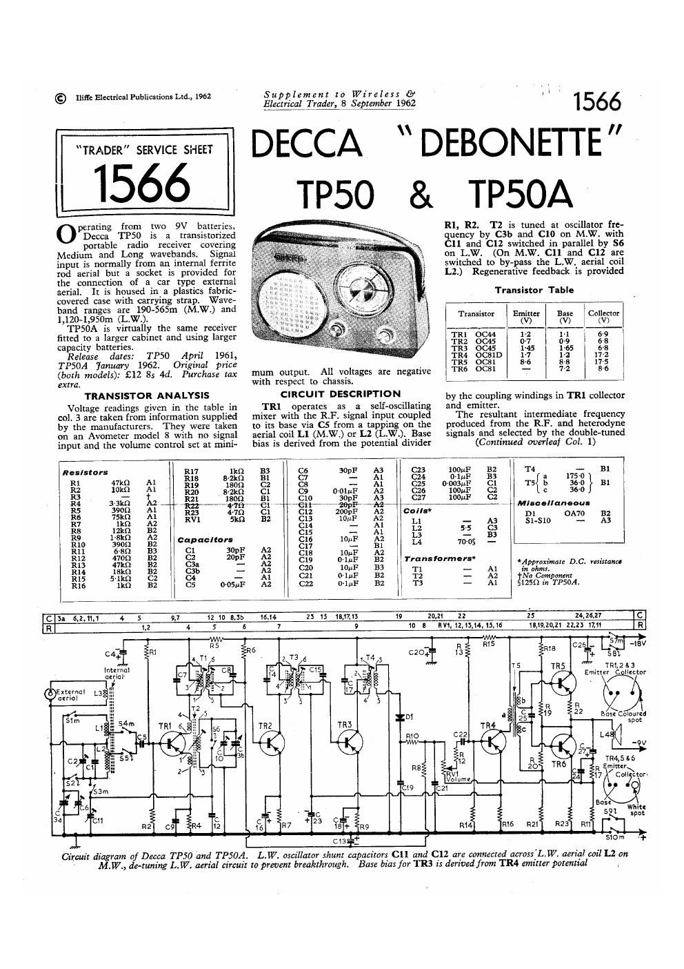
TRl operates as a self-oscillating
mixer with the RF. signal input coupled
to its base via C5 from a tapping on the
aerial coil Ll (M.W.) or L2 (L.W.). Base
bias is derived from the potential divider

1566

DEBONETTE "

TP50A

R1, R2. T2 is tuned at oscillator fre-
quency by C3!) and C10 on M.W. with
(311 and C12 switched in parallel by SS
on LW. (0n M.W. C11 and C12 are
switched to bypass the L.W. aerial coil
L2.) Regenerative feedback is provided

Transistor Table

Transistor Emitter Base Collector
(V) (V) (V)
4 12 1-1
0015 021 I as .
0045 ms 1'55
OC81D 1-7 1-:
coat 8-6 86
ocsi 7-2

by the coupling windings in 1111 collector
and emitter.

The resultant intermediate frequency
produced from the RF. and heterodyne
signals and selected by the double-tuned

(Continued overleaf Col. 1

I Resistors R17 (Q 33 06 30pF A3 C23 1001;? 32 T4 -- E!
R1 47m A1 R18 s-2kn 31 c: - Al C24 (HuF 33 a 1750
R2 10k!) A1 R19 1301) C2 05 ~ Al C25 0-005uF C1 T5 b 360 Bl
113 _ 1 R20 (Mk!) «:1 c9 D~01uF A2 cze 100uF C2 c 36-0
R4 3-3159 A2 R21. 150 31 C10 30pF A3 C27 11)ch C2
R5 390 A1 Rzr 'el 'ei -20pF-~Ak}~~' .~- ~ Misoollanooua
R6 75k!) Al R23 479 C1 C12 ZODpF A2 00. D1 OAT/0 32
R7 an A2 RV! 5m 32 EB 101i 1;} Ll - A3 I Sl-SlO - A3
s: an r - m t: s;
. 2 _
R10 390;) 32 c"°"°" E15; E Q? 1/! was -
fill 338 53 85 3395 2% -18 W M
P 4
R13 47m B2 C3: - A2 319 ° F 32 """°"°"' *Appmximau DIC. ruixtanco
mg 1st 32 csb - A2 20 10W 133 T1 - A1 in 01mm
R15 5le C2 C4 - Al C21 OluF B2 T2 - A2 {Na Component
R16 lkn 32 C5 0D5uF A2 C22 O'IMF 32 T3 - A1 1259 in TPSOA.
C II 6,2,1J 4 5 9,7 2 ID EJI) 15,14 Z3 15 18,17. 19 20,21 22 2.5 24.26.27 IC
R 1.2 4 5 6 7 9 10 B IV1. 12,13,14,15,16 15,19,211, 22,23 17,11 IR
s m
_ 1 C26 - L -lBV
R
c4+ - VB it: 581.
Internal 2 ms E Tat/(flit r
. m. at no
I7 I I §v A
O
a R
$19 22 Bos}Colour(s
TR} spot
L (I
V
g 29:
14,5:
TM R Emittzr
C / \
24 17 @Colljnort
\___'\_._ )
mud
Wh'tl
i 5 1 splat
an; R2! R23 mi 1"
[ 513%: ' ' l 510m ,1.

Circuit diagram of Decca TP50 and TP50A. L.W. oscillator shunt capacitors 011 and (:12 are connected acrosx'L.W. aerial coil L2 on

M.W., tie-tuning L. W. aerial circuit tn prevent breakthrough. Bate bias for TRS is derived from TR4 emitter potential

Page 2

Supplement to Wireless 6?
Electrical-[man 8 Septemlggggz

DECCA
TP50 & TPSOA

1566

Circuit Description-continued
transformer T1 in TRl collector circuit
is at 472kc/s. This is amplified by lst
and 2nd I.F. amplifiers TR2 and TR3
which are coupled by the LF. transformer
T3, and is then applied via T4 to the
detector diode D1. R4, R7 and R9 are
emitter D.C. stabilizing resistors.

The rectified audio output from D],
which Operates with slight forward bias
derived from the network R6, R8, 3V1
and R11, is developed across the diode
load resistor and volume control RVl.
The positive DC. potential present across
RVl as a result of rectified carrier cur-
rent is employed as AG.C. voltage and
fed back via R8 to reduce the gain of
the lst LF. amplifier TR2. .

From the slider of RV! the audio
signal is capacitively coupled to the driver
TR4 and from TR4 output, is transfor-
mer coupled via T5 to the bases of the
output transistors TRS and TRG. The
applied signal voltages are transferred by
the two secondary windings b and c in
opposite phase but equal in amplitude.
High impedance speaker L4 is'connected
as the output stage load impedance
eliminating the need of a separate out-
put transformer.

The lower end of the volume control
RVl is coupled to the junction R11, R17,
C24 to provide negative feedback.

CIRCUIT ALIGNMENT
Equipment Required.-An A.M. signal
generator; an AC. voltmeter for use as
an output meter; two resistors (lkfl and
21(9) and a bladed typc trimmmg tool.
1.-Switch to MAW. and Set the tuning
gang to the fully meshed posttion. Con-

Primad in Great Britain by Cornwall Press. Ltd.. Pa'n'x Garden, Stamford Street, London, 5.51.

Rear view of an up-
right TP50 chassis.
In the TPSOA the
battery brackets are
different, to accom-
modate the larger size
batteries, otherwise
the chassis are iden-
tical. Components
C12, C16, C18 and
R9 are located on
the chassis behind
C2 and C11. The
waveband switches,
drawn from the same
angle, are shown in
detail at the foot of
col. 2

External aerial
kzt

SO

flxu.-K

nect the signal generator across M.W.
aerial coil Ll: connect the AC. volt-
Elfter across the speaker speech coil

2.-Feed in a 472kc/s modulated signal
and maintaining the input only sufli-
ciently high to give a reasonable de-
flection in the output meter, adjust the
top and bottom cores of T1 and T3
and the core of T4 for maximum out-
put.

3.-Repeat operation 2.

4.-Connect the signal generator via the
21:0 resistor to the external aerial socket.
Tune receiver to 460m. Feed in a
652ke/s signal and adjust T2 and L1
for maximum output. Adjust Ll by
sliding its former along the ferrite rod.

5.-Tune receiver to 230m. Feed in a

SWITCH UNIT

Dorset Hausa. Stamford Street. London, 8.5.1

1,300kc/s signal and adjust C10 and C6
(osc. and aerial) for maximum output.

6.-Repeat operations 4 and 5.

7.-Switch to LW. and tune receiver to
1575mm. Connect the signal generator
Via the 1k!) resistor to the external aerial
socket. Feed in a l70kc/s signal and
adjust C11 and L2 for maximum out-
put. Note: When adjusting C11 there
may be a degree of oscillator pulling.
Care should be taken to adjust C11 and
L2 for maximum signal at the correct
tracking point.

8.-Tune receiver to 1,250m. Feed in a
240kc/s signal and adjust C2 for maxi-
mum output.

9.-Repeat operations 7 and 8.

GENERAL NOTES

' Dismantling-To remove the receiver
from its case proceed as follows: Remove
the back cover, unplug and remove the
batteries.

Pull off the transparent tuning knob and
slide off the tuning pointer.

Pull ofi volume and waveband control
knobs. Unplug the loudspeaker connec-
tions. Take out two hexagon headed
printed panel seeming screws (one each
side) and withdraw the chassis.

Switches.-Sl-S6 are waveband swit-
ches; 87-810 are battery (tn/off switches.
They are all combined in a three-position
rotary unit mounted on the printed panel
in location reference A3. A separate
diagram of the unit in col. 2 gives the
individual switch positions.

Batteries-Batteries recommended by
the makers are two Vidorrnax T6004
(TP50) and two Vidormax T6006 or Ever-
Ready PPS (TPSOA).

and Published by Iliflu Electrical Publications. Ltd"