Decca debonaire service manual

This is the 2 pages manual for decca debonaire service manual.
Read or download the pdf for free. If you want to contribute, please mail your pdfs to info@audioservicemanuals.com.

Page: 1 / 2
left right
decca debonaire service manual

Extracted text from decca debonaire service manual (Ocr-read)


Page 1

66 RADIO SERVICING

DECCA DEBONAIRE Model TP44

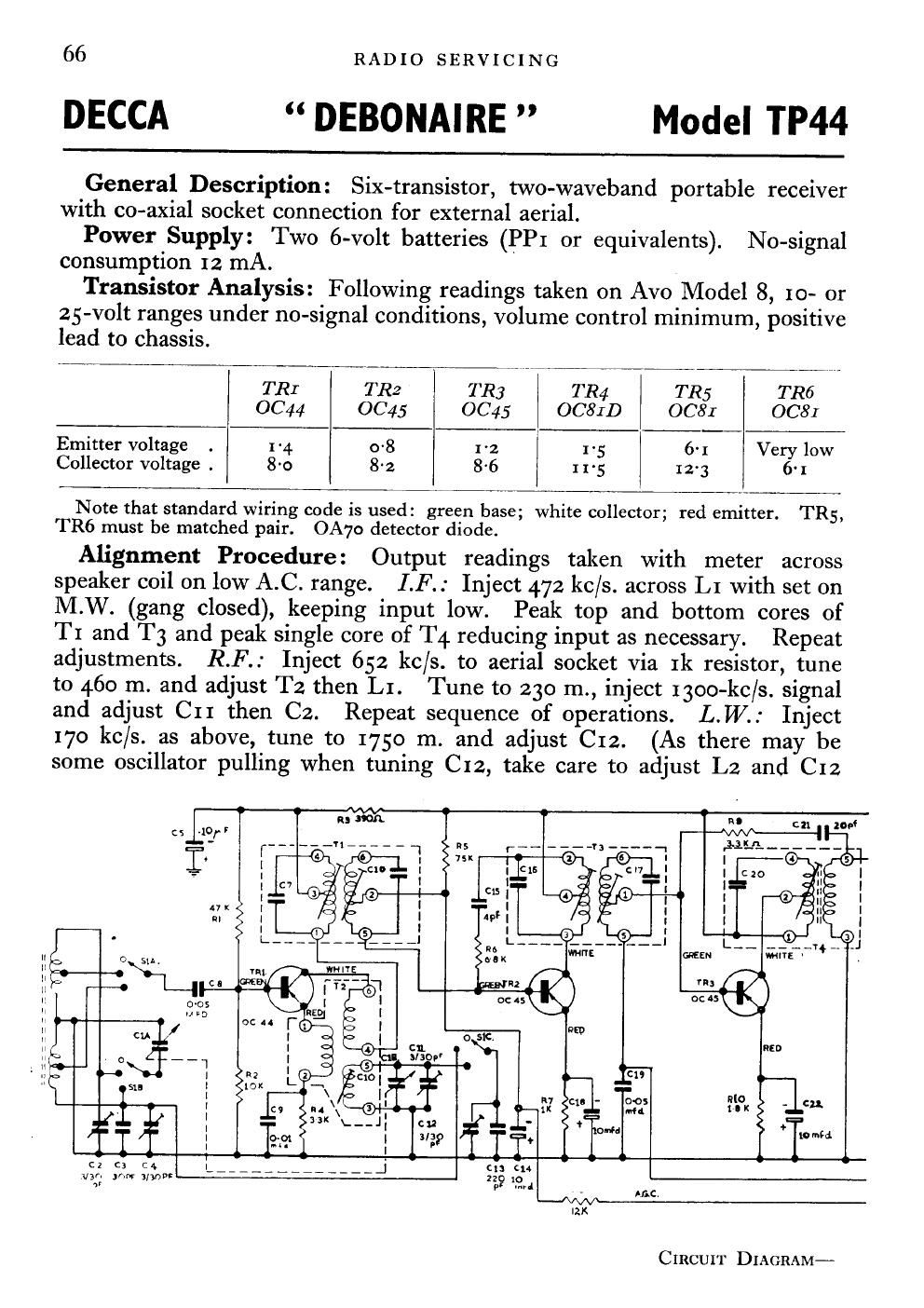
General Description: Six-transistor, two-waveband portable receiver
with co-axial socket connection for external aerial.

Power Supply: Two 6-volt batteries (PPI or equivalents). No-signal
consumption 12 mA.

Transistor Analysis: Following readings taken on Avo Model 8, 10- or
25-volt ranges under no-signal conditions, volume control minimum, positive
lead to chassis.

TRI TR2 TR3 TR4 TR5 TR6

0044 0045 OC45 OC8ID OCSI 0081
Emitter voltage . 1-4. 0-8 1-2 I 1- 5 6-1 Very low
Collector voltage . 8-0 8-2 86 11-5 12-3 61

Note that standard wiring code is used: green base; white collector; red emitter. TR5,
TR6 must be matched pair. OA7o detector diode.

Alignment Procedure: Output readings taken with meter across
speaker coil on low A.C. range. I.F.: Inject 472 kc/s. across L1 with set on
M.W. (gang closed), keeping input low. Peak top and bottom cores of
T1 and T3 and peak single core of T4 reducing input as necessary. Repeat
adjustments. R.F.: Inject 652 kc/s. to aerial socket via 1k resistor, tune
to 460 m. and adjust T2 then LI. Tune to 230 m., inject 13oo-kc/s. signal
and adjust C11 then C2. Repeat sequence of operations. L.I/V.: Inject
I70 kc/s. as above, tune to 1750 m. and adjust C12. (As there may be
some oscillator pulling when tuning C12, take care to adjust L2 and C12

f I

C 2 :3 C 4
van )0! 3/30
a:

IZK

CIRCUIT DIAGRAM-

Page 2

COMPONENT
LAY- OUT

for maximum 'Signal at correct tracking point.) Tune to 1250 m., inject
24o-kc/s. signal and adjust C4. Repeat sequence.

Servicing Notes: Take great care not to scratch or chip the paint
covering on the transistors. When soldering use reasonably sized pair of
pliers as heat sink. Electric soldering-irons should be earthed, as irons
often have a very slight leak when hot, and the resultant current can damage
a new transistor.

Component Notes: Loudspeaker impedance 25 ohms. On some models
C30, shown dotted in circuit diagram, has been added in base circuits of
output stage. This may be either 500 pF. or 1000 pF. and has been added
to neutralise phase-shift effects of T5 when necessary. C3, C13, R20, R22,
R23, R24 5%. C21 2%. C15 4 pF. :1: % pF. RV: 5k linear potentio-
meter. =

NW . sin.
14 1.5K

-‚¬29. MFD
om. too
+ -

DECCA DEBONAIRE MODEL TP44