Decca dauphine service manual

This is the 4 pages manual for decca dauphine service manual.
Read or download the pdf for free. If you want to contribute, please mail your pdfs to info@audioservicemanuals.com.

Page: 1 / 4
left right
decca dauphine service manual

Extracted text from decca dauphine service manual (Ocr-read)


Page 1

V Supplement to Electrical and Electronic Trader
17 September 1 971
©LP.C. Business Press Ltd.

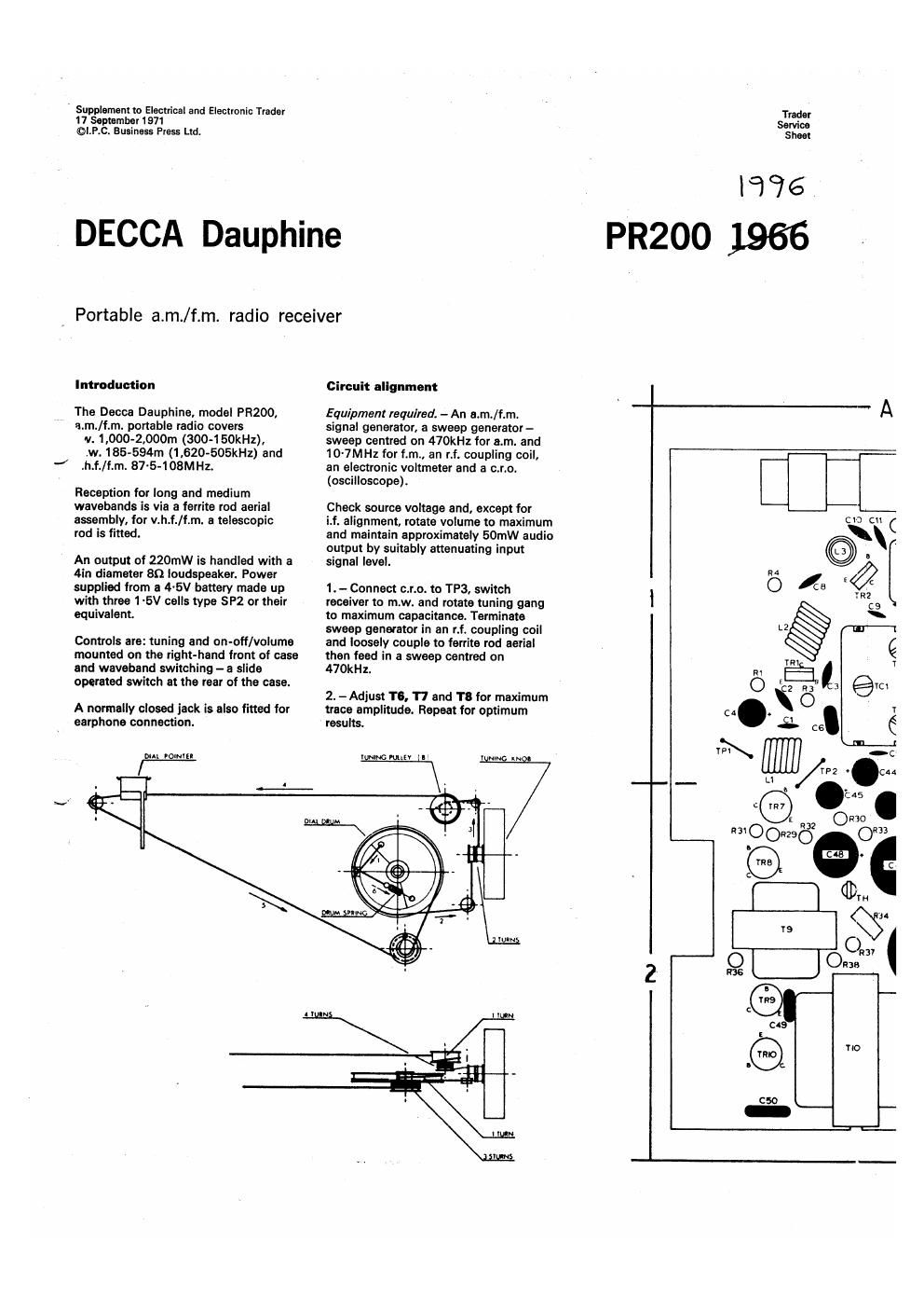
DECCA Dauphine

Portable a.m./f.m. radio receiver

Introduction

The Decca Dauphine, model PR200,
a.m./f.m. portable radio covers
v. 1.000-2,000m (300-150kHz).
cw. 186-594m (1 .620-505kHz) and
.h.f./f.m. 87~5~108MH2.

Reception for long and medium
wavebands is via a ferrite rod aerial
assembly, for v.h.f./f.m. a telescopic
red is fitted.

An output of 220mw is handled with a
4in diameter 89 loudspeaker. Power
supplied from a 4-5V battery made up
with three 1~5V cells type SP2 or their
equivalent.

Controls are: tuning and on-otf/voluma
mounted on the right-hand front of case
and waveband switching - a slide
operated switch at the rear of the case.

A normally closed jack is also fitted for
earphone connection.

em romrtl

Circuit alignment

Equipment required. - An n.m./f.rn.
signal generator, a sweep generator-
sweep centred on 470kHz for em. and
10-7MHz for f.m., an r.f. coupling coil,
an electronic voltmeter and a c.r.o.
(oscilloscope).

Check source voltage and, except for

it alignment, rotate volume to maximum
and maintain approximately 50mW audio
output by suitably attenuating input
signal level.

1. -Connact c.r.o. to TP3, switch
receiver to m.w. and rotate tuning gang
to maximum capacitance. Terminate
sweep generator in an Lt. coupling coil
and loosely couple to ferrite rod aerial
then feed in a sweep oenued on
470kHz.

2. - Adjust T6. 17 and T8 for maximum
trace amplitude. Repeat for optimum
results.

Trader
Service
Sheet

lcfié

PR200 1966

_.

TlO

Page 2

Vintage Service Data CD-Flom

Electrical and Electmm'c Trader l7 Swrembzr [971

Q 3.-Transfer r.f. coupling coil to signal
generator, disconnect c.r.o. and connect
an electronic voltmeter across
loudspeaker voice coil. Loosely couple
signal generator output to ferrite rod
aerial assembly.

4. -Tune receiver to 594m and feed in
a 505kHz a.m. signal. Adjust L7 for
maximum output.

5. -Tune receiver to 182m and feed in
a 1.650kHz a.m. signal. Adjust TOG for
maximum output.

6. - Repeat operations 4 and 5 to obtain
frequency range.

Decca Dauph/ne, modal szoo

7. - Tune receiver to 500m and feed in

a GOOkHz am. signal. Adjust position of
L5 on ferrite rod for maximum output.

8. -Tune receiver to 214m and feed in
a 1,400kHz a.m. signal. Adjust 1'04 for,
maximum output.

9. - Repeat operations 7 and 8 as
necessary to minimize tracking errorr also
operation 5 it found necessary.

10. - Switch receiver to l.w. and tune
to 2,143m. Feed in a 140kHz a.m. signal
and adjust L6 for maximum output.

11r-Tune receiver to 968m and feed in
a 31 OkHz e.m. signal. Adjust Tea for
maximum output.

Continued overleaf Cal. 1.

A l B


'V

L5

L8

CV3\C\IOR5

R7 R6

Wllllll l

WAVE CHANGE SWITCH I: O

1C3

www. vin tage-ra dio. com