Decca capri majorca service manual

This is the 2 pages manual for decca capri majorca service manual.
Read or download the pdf for free. If you want to contribute, please mail your pdfs to info@audioservicemanuals.com.

Page: 1 / 2
left right
decca capri majorca service manual

Extracted text from decca capri majorca service manual (Ocr-read)


Page 1

Supplement to Electrical and Electronic Trader Trader
7 March 1969 Service
© l.P.C. Business Press Ltd Sheet

Decca RP199 Capri 1894
& RP200 Majorca

Portable transistored record players

Introduction

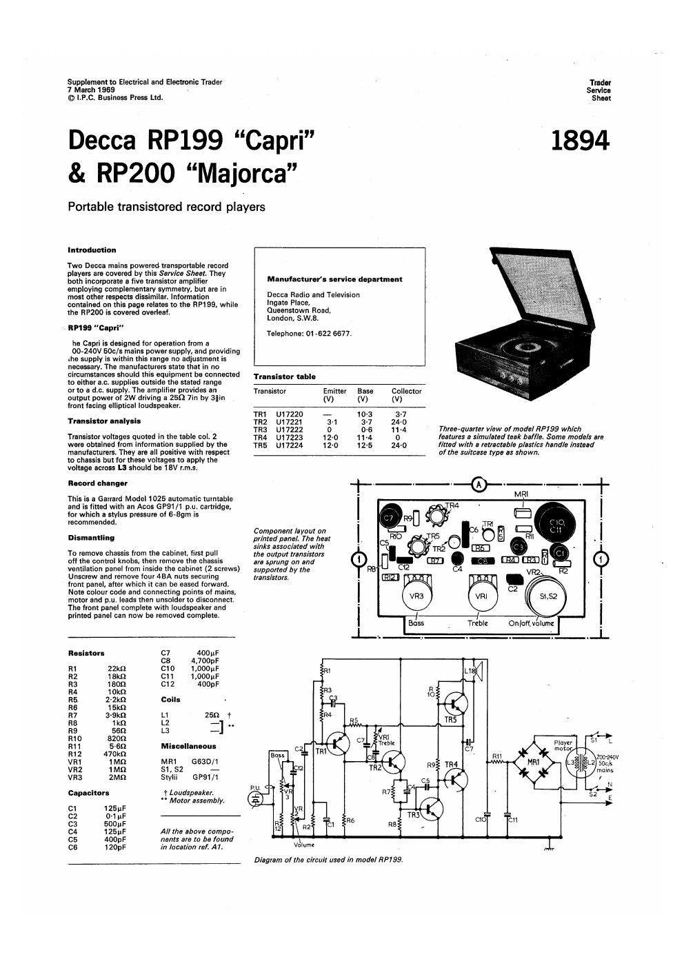
Two Decca mains powered transportable record
players are covered by this Service Sheeh They

both incorporate a live transistor amplifier Manufacturer! urvlea den-rtmnt
employing complementary symmetry, but are in ~ .

most other respects dissimilar. Information Decca Radio and Televrsion

contalned on this page relates to the RP199, while '"9318 Place,

the HPZOO is covered overleaf. 0059"!!er Road,

London, SrW.Br
-_ times "ea
9" Telephone: 01-622 6677.

he Capri is designed for operation from a

00-240V 5013/3 mains power supply, and providing
.119 supply is within this range no adjustment is
necessary. The manufacturers state that In no
circumstances should this equipment be connected Trans' (or
to either a.c. supplies outside the stated range

or to a de. supplve The amplifiel provides an Transistor Emitter Base Collector
output power at 2w driving a 25K] 7in by Stin (v) (v) (v)
lront lacing elliptical loudspeaker.

TRI U17220 -- 103 3'7
77.1553? inllYiiS TRZ U17221 31 3-7 24-0

TR; u17222 o 0.5 1 1 4 Three-quarter View of model RP199 which
Transistor voltages quoted in the table col. 2 TR4 u17223 12-0 11.4 0 features a simulated reek ball/e. Some models are
were obtained from information supplied by the ms U17224 1210 12.5 24-0 lined with a retractable plastics hand/e instead
manulacturers. They are all positive with respect _____-__ o! the suitcase type as shown.

to chassis but for these voltages to apply the
voltage across L3 should be 18v rims.

Record changer

This is a Garrard Model 1025 automatic turntable

and is titted with an Acos GP91/1 p.u. cartridge, I
[or which a stylus pressure of 6-8gm is
recommended. '
Component layout on I
Dismantling printed panel The hear ~ .
sinks associated with .
To remove chassis lrom the cabinet, first pull the output anxiety 8
on the control knees, then remove the chassis m mung 0,, and CE
ventilation panel lrom inside the cabinet (2 screws) suppaltad by me VR2
Unscrew and remove tour 45A nuts securing enemys, . -
front panel, after which it can be eased forward. -
Note colour code and connecting points at mains, I K . I
motor and p.u. leads then unsoldar to disconnect > .
The front panel complete with loudspeaker and '
printed panel can now be removed complete. I ,1 ,
Boss Treble Onlotl olulnz _
i . . A ._L
Resistors C7 40011 F
C8 4,700p F
m 22m CID 1,000»; m L,
R2 13m C11 1.00015
R3 1 809 Cl 2 400pF
R4 1 Okfl
R5 Z-Zkfl Coils -
R6 1 5m
R7 3-9kfl L1 2551 1
R3 1 kn L2 -] . .
R9 550 L3 -
R1 0 8209 Fla e r
R11 51m Miscellaneous Y
R1 2 470K! _
vm an MR1 5630/1 -33?
VRZ 1Mfl S1, 52 - molns
VR3 2M0 Stylii GP91/1
N
capacitor: 1 Loudspeaker.
" Motor assembly. E
Cl 125;»:
c2 0-1 pF
C3 500D}:
or new: All the above compo-
05 4009F Ire/rt: are to be lounti ' l ,
C6 120pF in location ref. A11 1,

Diagram of the circuit used in model nPlss.

Page 2

Vintage Service Data CD-From

Electrical and Electronic Trader 7 March. l969

1894

Decca RP199 8- RPZOO

RPM "Melon."

The Meiorca is designed tor operation from
200-Z4OV 6013/: mains power supplies, with the
same limitations that apply to model RH 99
(see overleaf).

This raproducer has a miniature jack fitted

enabling a tape recorder to be connected (via a
3-5mm long shank lack plug) for both record and
playback. it presents an Impedance of approximately
20m and a sensitivity of approximately toomv

for both conditions

Aforwsrd facing sin by 5in elliptical loudspeaker
handle: an audio output power oi 3W.

Trenalnor analvels

Transistor voltages shown in the table below
were obtained from information supplied by the

manuhcturors and they are all negative with
respect to positive line.

Record changer

The automatic record changer is the Gerrard
model 2025 which is fitted with a loiin die.
turntable. An Ace: GP91 ll SC p.u. cartridge is
fitted, the recommended stylus pressure being
6-89111. The ou. is mono/stereo compatible and
will track satisfactorily on both mono errd stereo
records without damage to either.

Blemamllng

To gain access for servicing, fim remove
loudspeaker and printed panel cover from lnsltlo
cabinet (4 screws). than pull off knobs. Unscrew
four screws securing motor board to cabinet,
draw motor board forward out oi recess in cabinet
rear and with the left-hand side tilted upwards
slightly. Iilt motor board out to the extent of
connecting leads. Unscrew and remove two
binder screws located at the top right-hand end
ol cabinet cross- member behind control knobs.

The printed panel may now be removed to the
extent of the loudspeaker lead:

Appearance of model RPZOO. The tape jldr end
neon indicator lamp are clearly seen on the lclr
or the upward: lac/n9 coma] lac/a. not eppmnr
is the lid which I: upliu/flmd in vinyl.

Plan View of I
component side of

pr/ntad panel. The

output trans/store 0/
this modal are bolted
on to the heat sink.
which also twist: in
maintaining the printed '
panel lipid. l

.
Volume I Bass ! Onloii.trci>l¢
. I . ,. | . . . ._L
Tranaimr table Resistors R11 1511 C1 Genocitors Miscellaneous
R12 1-5m 31 (:1 WWW ..
Traneistor Emitter Base Collector R13' 1m 51 ca 01uF C1 SR1 BYtzz A1
(V) (V) (V) R1 150m 01 R14 3901': El 04,, 00; c1 TH1 VA1077 31
R2 ma (:1 R15 1000 A1 cs 'o-1uF B, 51.52 - c1
TR1 Bczea 16-0 14-5 7-6 R3 10m (:1 R16 33m 131 cs 40 B1 Stylii GP91/1sc -
rRz Bczss 11-5 7-5 0-2 R4 56m c1 R17 1001': B1 c7 (MUM: c1
TR3 Ac142 o 0-2 118 R5 1-5119 01 R18 2-211 B1 ca 0.22;; M
TR4 Ac142K 12-0' 12-2 24-0 Rs 68m (:1 R19 2-2.0 131 C10 170uF at
me AC141K 12-0' 11-8 0 R7 33m C1 1120 1-2m " c" 50,; c1 .
Ra 39m c1 VR1 20m 131 C12 7",: a1 M-ybebam.
'Measuredbetwaantha/unctianafR18/R19 Rs 390m (:1 VRZ 100m c1 (:13: 170% C1
andchnseis. R10 270m (:1 VR3 50m Al iMlybc¢700M

R31] C10
< R1
Bass
TR
R
C5
cs
r-fl-r
C7 Tape
socket.

3/ 5 R4
VRZ


Treble

C14 820pF Bl
C16 mm Al
Cl6 400w A1
(:17 2.0qu A1

3 My be 1505:-

" Wired on recon!

Coils , player assembly.
L1 ff Loudspeaker.

L2

L3 5 § Motor assembly.

Circuit diagram a!
model RP 200
"Majorca".

Prlnted in Great Britt/n by Gnome Rose Printers. Nursery Rood/Zion Road. Thornton Heath, Surrey. and Published by I.P.C Electrical 'Electronlc Press Ltd., Dorm

Hausa. Stamlard Street. London, 3.5.1.

www. Vin tage-ra dio. com