Decca aw3 aw3p aw47 awd 47 brunswick service manual

This is the 4 pages manual for decca aw3 aw3p aw47 awd 47 brunswick service manual.
Read or download the pdf for free. If you want to contribute, please mail your pdfs to info@audioservicemanuals.com.

Page: 1 / 4
left right
decca aw3 aw3p aw47 awd 47 brunswick service manual

Extracted text from decca aw3 aw3p aw47 awd 47 brunswick service manual (Ocr-read)


Page 1

IOIIIIIIIIIIIIBIIMIIII'IIIIIIIIIIIIIIIHIIIllII!||!||II!||(IIIII(II!(IIIIIIIIERIIUIIIIINIIII(IIIII|||(NIIIIIIIIIIIIILIIIIIIIIItllflllllflll!

TRADER SERVICE SHEET

576 '

Ill1iIIIiIllliIlli1IINIIIIN'IIIIIIHIHIillIllllllliilllllliillliIII!IIII(IIIIIIIIIiIIIlllllllllliIIUI||||Ii||H[IliHIHIIIIW!IIUHI(IIIIU

The Decca AW3 receiver.

variable-mu characteristics in the

pentode section, is used in a reflex
circuit in the Decca AWS to provide IF
amplification, signal detection, AVG and
AF amplification.

The receiver is a 3-valve (plus rectifier)
3-band transportable superhet, designed
to operate from AC or DC mains of 200-
250 V, 40100 0/3 in the case of AC. The
SW range is 16-50 m. ,

Selfrcontained MW and LW frame
serials are fitted to the back of the cabi-
nE and the pick-up from them may be
used for SW operation. Sockets are also

A DOUBLEQIODE RF pentode, with

L3 Cl :15 51

Supplement to The Wireless (5*
Electrical Trader, july 4, 1942

DECBA AW3, AW3P, AW

Ann BRUNSWICK AW47 ,,

provided for the connection oi an external
aerial and an earth, and for a gramw
phone pick-up of the crystal type.

The Decca AWSP is a similar receiver
but is fitted in a portable carrying case
with a carrying handle.

The Decca AWD47 and Brunswick
AW47 are table radiograms, equipped
with cr stal pick-ups They employ an
identical type of chassis, hut gram
switching is fitted on the motor boards

Release dam, all models: 1940,

CIRCUIT DESCRIPTION

0n MW and LW, input is from tuned
frame aerial L1 (MW), La (LW) and 021
to triode hexode valve (V1, 0mm X65),
which operates as frequency changer with
internal coupling, Two sockets are pro
vided on the irame aerial assembly for
the connection of an external aerial and
an earth, and when they are used, coup-
ling is effected via L1. which consistsof
a few turns of wire in the MW frame
winding. The sockets are isolated from
chassis by GI.

Ou SW, input from external aerial is
via L1 and the SV coupling coil LA to
single tuned circuit L5, 011. The frame
aerial can be used ii desired for SW re-
ception, when the pickup from the frame
aerial is transferred to LII via L1. ,.It

should be noted that in this instance the

SW circuit is shown in the circuit dia
gram beneath the MW and LW circuit,ra's
otherwise the input circuit would have}
appeared rather complicated -
V1 triode oscillator control
coils L6 (MW), L1 (LEV) an L8»(SW)7
are tuned by 028. Parallelrtrimmiu l: I
029 (MW), ca, 030 (LW) and 031 (S );
series tracking by 01 (MW), 08 (LW) and
09 (SWI. It will be observed that the
SW circuit is again beneath the MW and
LW circuits in order to agree with the '
aerial circuit arrangementsr Reaction '
from anode is via coils L9 (MW and.
LVV) and L1!) (SW).
Second valve (V2, Brimnr 638G) is a
double diode variable-mu RF pentode
operating in a reflex circuit or inter-
mediate ircquency amplifier, signal d '
teeter, AVG rectifier and AF amplifier. ,
IF signals in V1 hexede output are
applied to V2 pentode control grid circuit
via, a tunedprimary, tuned-secondary
transformer, (:32, L11, L12, 033, and the
IF output from V1 pentode is developed
across a. tunedrprilnary transformer 9/,
L13, Lil. ' '

Intermediate frequency 380 Kc/S.

The output from L14 is applied via on
to the signal diode of V1; the audio fre:
quency component in the rectified output
is developed across load resistance R1

rid circuit ,'


as

an n

WHITE/MACK
:0 ' want/him
cw
PU
c 4 Mo SCRIENED mos

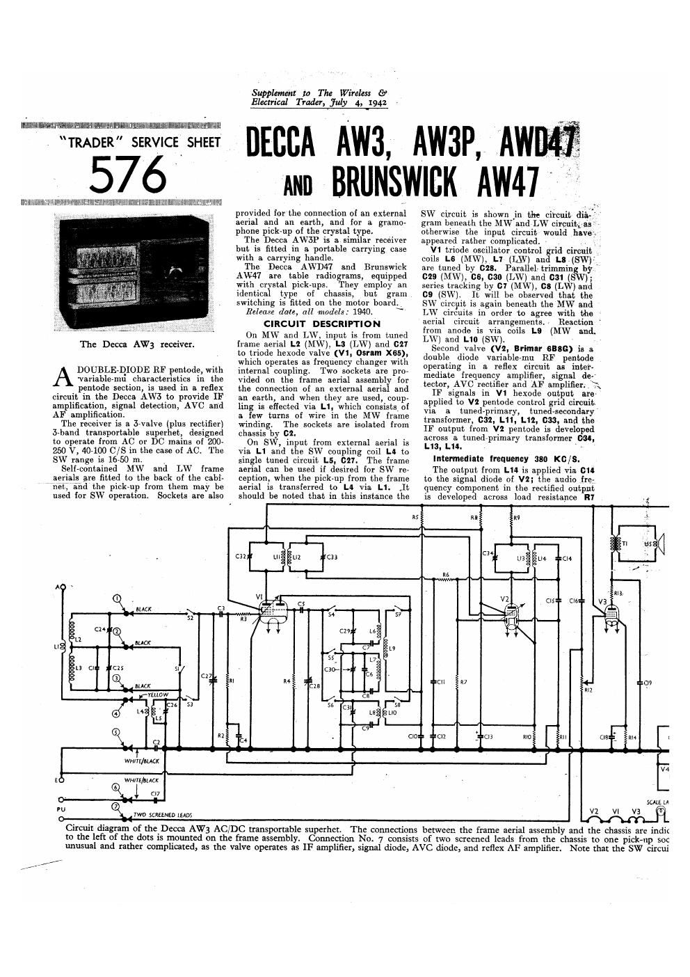
Circuit diagram of the_Decca AW3 AC/DC transportable superhet, The connections between the frame aerial assembly and the chassis arc indir
to the left of the dots is mounted on the frame assembly, Connection No. 7 consists of two screened leads from the chassis to one pick-up sec
unusual and rather comphoated, as the valve operates as IF amplifier, signal diode, AVC diode, and reflex AF amplifier. Note that the SW circui

Page 2

Vintage Service Data CD-Rom

.
l
x
l
l
l
:

Under - chassis
view. In several
cases components

" are hidden, and

are indicated by

broken . lines.

Some of the

, aids to the frame

assembly are

shown, and they

are traced to

- their connecting
ta . A detailed
diagram of the
Sr-ss switch dia-
gram appears in

C01. 4 overleaf.

--;__---....,-_.__._._


(.-.-....--

t'

and passed via coupling resistance R6 and
transformer secondary L12 to CG of-pen-
.tode section, which operates as reflex AF
amplifier, with R9 as its AF load resist-
ance. IF filtering by R6, 011. As there
isgIfC/ continuity between the signal diode
fa'node and the pentode control grid, the
DC potential developed across R1 is
applied as GB to the pentode section of
the valve, providing automatic volume
control in this stage.

Secon'd diode of V2; fed from L" via
on and 015, provides a further DC poten-
tial which is developed across load re-
sistance R11 and fed back through a de-
coupling circuit as GD to the FC valve,
giving automatic volume control for that
stage. Both diodes are delayed by the

AC or DC
MAINS

A 9

e chassis are indicated by dots and arrows, and everything

0 one pink-up socket.

The circuits associated with V2 are

hat the SWcircuits are beneath the MW and LW circuits.

Supplement to The Wireless {9
Electrical Trader, fuly 4, 1942

voltage drop along [110 in V1 cathode
lead to chassis. -

Resistance-capacity coupling by R9,
(:16 and the manual volume control R12
between V2 pentode and pentode output
valve (V3, 0mm KT350 or KTSSG).
Fixed tone correction by 019 in anode
circuit.

Provrsion is made for the connection of
a gramophone pick-up across R12, and
the earthy lead is returned to chassis via.
an isolating condenser 01". As the
sockets are mounted on the frame aerial
assembly, they are shown in the circuit
diagram in this position, the connecting
points between them being indicated by
dots and arrow-heads which are in line
with the other five frame aerial/chassis
connecting points.

When the receiver is operated from A0
mains, HT current is supplied by an in-
directly-heated half-wave rectifying
valve (VII, Osrem ua1 or Brimar 2515)
which, with DC mains behaves as a low
resistance. Smoothing is effected by an
iron-cored choke L16 and dry electrolytic
condensers 020 and 011. If the Brimsr
2513 is fitted, its two halves are con-
nected in parallel to operate as a half-
wave rectifier.

Valve heaters, together with scale lamp
(which is at high AC potential from
chassis) and heater circuit ballast resist-
ance R15, are connected in series across
the mains input circuit, Mains circuit RF
filtering by 022 and 023.


CONDENSERS Values
(MF)
C1 Frame serial LW fixed
trimmer 0000025
C2 Earth Isolating condenser 00!
(:3 V1 hex. CG condenser 0'0001
C4 Vl. hex. CG decoupling... 002
C5 V1 osc. CG condenser 0 0001
CS 050. cite. LW fixed trlm- >
met 000015
07 05c, cite. MW tracker 00007855
CS Osc. circ. LW tracker 00003855
C9 050. the. SW tracker 0004
010 V1 osc. anode decouplln 0-1
011 [F by use . 0-0002
C12 V2 cat ode biz-pass 0-1
013 V1, V2 86s decoup mg 6-0
C14 Coupling to V2 signal .
diode 00002
(715 Coupling to
diode , 0-0001
016 V2 [tentacle to
coupling 0-001
017 PU isolating condenser 002
C18 V3 cathode bY-pass 50'0
019 Fixed tone Corrector 0-001 1
020' HT smoothing con- 20 1
021' densere 32-0
(:22 Mnlns RF by-pesa con- 0-02
C23 densers - 0-02
024: Frame aerial MW trlm- l
mer
C253 Frame aerial LW trimmer
(:26: Aerial clrc. SW trimmer
0271 Aerinl tuning condenser
(:28 Oscillator circuit tuning --
029, o l trimmer -
0301 LW trimmer -
031: o ,. .sw trimmer - l
032: in IE trans. pn. tuning -- 3
033: m 1r trans. sec. tuninll - 1
034: 2nd 1F trans. pn. tuning _

Electrolytic. 7 Variable. tv Pro~set.
§ 0000685 F + 00001 uF connected in parallel.
1 Two trimmers connected In parallel.


f 7" " AWE
COMPONENTS AND VALUES 0 °°MP°MMS ($.12?
; z - ~ .
RESISTANCES Values £é External aerial coupling (23;
(ohms) . L3 l Frame aerial windings ...{ 5,5 .
7-#- - IA Aerial sw couplin coil 2-4
R1 V1 CG hex. resistance l 470.000 l L5 I Aerial sw tuning cgoil . - Very low
- 112 v1 cc hex. decoupling . . 470,000 L5 ; 05M, winning 1 2.4 l
i R3 v1 gnd stopper .. l 40 1 L7 i 05c. ci w tuning . 5-2 l
m \ v1 (mac-Greenhouse . . 47,000 = L8 1 056.01 .swmmng Very low
v R5 - V1 mar-ode HT read ~ L9 02c. MW and Lw Ie- .
i no i AF couplmgtovz penwde action 1 7-2
. R7 V2 51 m1 diode load » L10 Osc. sw rcactinn 04
. m l 2 so 3 HT reed L11 . 1a,: 3.5
l in v2 pentode AF loud m 1 N m 15- {Sec' 10-0
l mo v2 fixed on resistance L13 Pn 19-0
. 311 v2 avc mode load L 2nd IF trans. Sec: 5.0
l 1112 Manual volume control . 5 8 cake: speech can 2.5
fig :3 $113023;ng Lie 1 smoothing choke 400-0
. , ., ,
R15 . Heater circuit ballast T1 5mm mm £1; 1 3333

'Tapped 3 70 0+70 0+310 0+120 0
from V4 heater end. Tap at 310 0 not used.

www. vin tage-ra dio. com

trans. e
Sl-SB - Wavelvanrl switche ..
Mains switch, ganged 112