Decca aw 4 service manual

This is the 3 pages manual for decca aw 4 service manual.
Read or download the pdf for free. If you want to contribute, please mail your pdfs to info@audioservicemanuals.com.

Page: 1 / 3
left right
decca aw 4 service manual

Extracted text from decca aw 4 service manual (Ocr-read)


Page 1

H (Supplement)

TRADER' SERVICE SHEET

j 34| '

is covered by the Decca AW4

4-valve (plus rectifier) AC/DC 3-
band superhet. which is suitable {or
mains of 190-250 V (50-60 C/S in the case
01 AC). Provision is made (or the con»
nection of both a gramophone pick-up
and an extension speaker.

CIRCUIT DESCRIPTION

Aerial input via series condenser 01
and coupling coils L2 (SW), L4 (MW)
and (via 342 metre rejector circuit
L1. 03) L8 (LW) to single-tuned circuits
L8. 031 (SW). L5, 031 (MW) and L7,

, 031 (LW).

First valve (V1, Mazda metanised
T355320) is a triodehexode operating as
frequency changer with internal coupling.
Oscillator anode coils L9 (SW). L11

.(MW) and L13 (LW) are tuned by
C37; parallel trimming by 032 (SW),
033 (MW) and 034, 011 (LW); series
tracking by (:9 (SW), 010, 035 (MW)
and 036 (LW). Oscillator grid reaction
coils Ls (SW), L10 (MW) and L12 (LW).

A- SHORT-WAVE range of 19-49m

THE WIRELESS & ELECTRICAL TRADER

August 13, 1938

DECCA AW4

3-BAND AC/DC SUPERHET

Second valve, .1 variable-mu RF
pentodc (V2, Mullaril metellised VP130),
operates as intermediate frequency
amplifier with tuned-primary tuned -
secondary transformer couplings 038,
L14, L15, C39 and C40, L18, L17, 041.

Intermediate frequency 465 KC/s.

Diode second detector is part of
separate double diode valve (V3, Brimar
10D1). Audio frequency component in
rectified output is developed across load
resistance £11 and passed via stopper
resistance RIO, AF coupling condenser
016 and manual volume control 312
to CG of pentode output valve (V4,
Mullard Pen36c or Brimar 7D6). Fixed
tone correction in anode circuit by 022.
Variable tone control by 041 across 312.
Provision {or connection of highimpedance
external speaker across primary of
internal speaker input transformer T1.
Provision for connection of gramophone
pick-up across R12, via isolating con-
denser 017.

Second diode of V3, fed from tapping
on L17 Via 018, provides DC potential
which is developed across load resistance
R13 and fed back through decoupling
circuits as GB to FC and 11" valves,
giving nnuunnur unlinnc control. Duluy
voltage is obtained irom drop across V4
cathode resistances R14, 315.

When the receiver is used with AC
mains HT current is supplied by a hali~
wave rectifier (V5, Brimu 1135 or Muliald
URIG) which, with DC supplies, behaves
as a low resistance Smoothing is effected
by iron lytic condensers C23, 024.

Valve heaters are connected in series
together with current regulating barretter

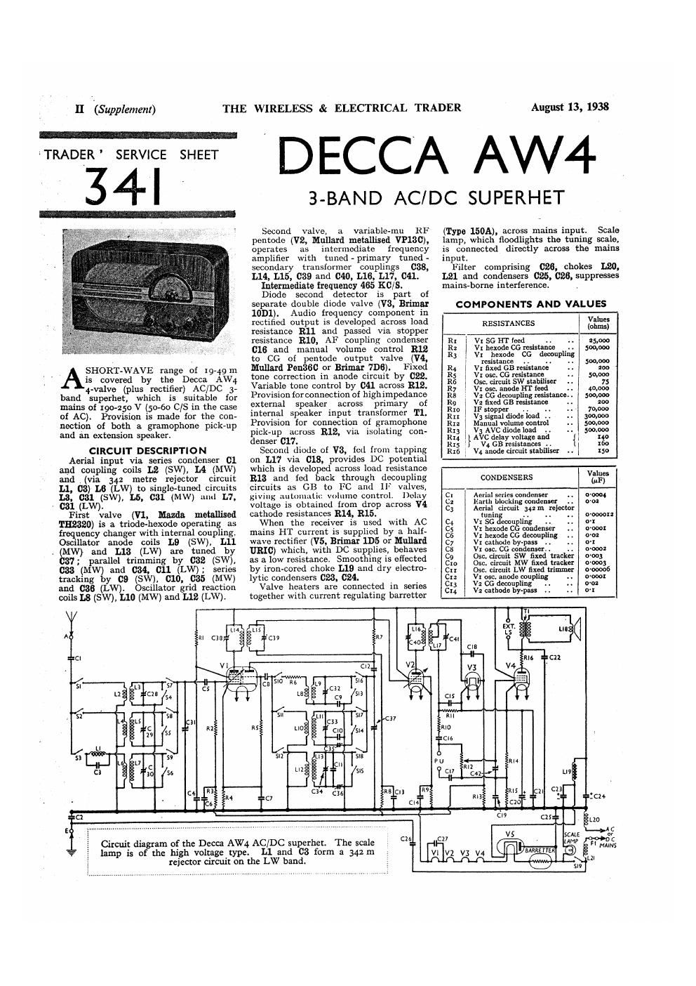
Circuit diagram of the Decca AW4 AC/DC superher. The scale

lamp is of the high voltage type.

L1 and 03 form a 342m

rcicctor circuit on the LW band.

(Type 150A), across mains inputr Scale
lamp, which floodlights the tuning scale,
is connected directly across the mains
input.

Filter comprising 028, chokes L20,
L21 and condensers 025, 026, suppresses
mains-borne interference ,

COMPONENTS AND VALUES

RESISTANCES Km

Rr ViSGI'lTieed ., . 25,000
K: I vinexodeocresirtam 509.000
R3 , Vr hexode cc dwoupling

. resistance ., ..
R4 \ VrflxedGBreslstanee
R5 onsc.CGresistance
R6 ; 0:0.clrcuitSWstahiliser

R7 . V! are. anode in feed ._
R8 V2 cc decoupling resistance.

R9 , v; fixed on resistance

Rro 1r stopper .. ..

Rn v3 signal diode load ,.

Ru 1 Manual volume control

R13 vaAvc diode load ..

Ru }A c delay voltage and { no

R15 V4 GB resistances .. x60

R16 vi anode circuit stabiliser .. :50
Values

CONDENSERS (#1,)

Cl Aerial snriur oondcnnr Wm

c: mm. blocking condenser . . on:

C3 Aerial circuit 342 m rejector

tuning .. . i . . D'oooou

C4 Vx so decoupling .. 01

C; v: hcxode cc condense wow!

cs Vr hexode cc decoupling 0'02

C7 Vr cathode by-pass i. . 0-!

cu vi use, cc condenser. .. o~oooz

C9 050. circuit sw fixed tracker woo;

Gm 051:. circuit mw fixed tracker 0-0003

Cu Osc. circuit LW fixed trimmer 000006
Cu V! use. anode coupling

C13 v: cc deeou ng

cu v: cathode hy-pasx

Page 2

August 13, 1938

Under-chassis
view. Diagrams
of the two
switch units, as
seen in the direc-
tions of the
arrows, are on
page IV. Note
the six coil units
with one trim-
rncr above each.
F]. is mounted
above L21.

THE WIRELESS & ELECTRICAL TRADER

CONDEgvSERs Values
(Commit) (or)
0x5 lF lay-pass . . o~oooi
C16 AF coupling to V4 . we:
on PU isolating condenser 0-0:
6:8 Gougllni to V3 AVC diode 040001
erg v. c ecoupliug . 01
cm vi Cathode by-pnss .. .. 00
Car V3, V4 cathodes RF lay-pass. . niooar
82. V4 anode tone correcior . , 0-006
3 8'0
2. }m smoothing ,. { 16,0
egg }Malns RF filter condensers { 3:36
C27 Vr heater RF h -pnss o-ox
Cos Aerial circuit 5 trimmer .. -
C29 Aerial circuit MW trimmer .. -
Cso Aenal circuit LW trimmer . -
631 _circult tuning. . --
Cal: Osawouit SW trimmer -
033: Om. circuit MW trimmer
C343 Osc. circuit LW trimmer
C35: 05¢. circuit MW tracker
C36 Olin. circuit LW tracker
C371 0m circuit tuning
can an IF trans. pri. tuning ~
C391 ist [F trans. seer tuning --
64o: and in inns. pri. tuning -
cm 1nd IF trans. seer tuning -
Cut Varlable tone control. . o-ooos
' Electrolytic. 1 Variable. : Pie-set,
Approxr
OTHER COMPONENTS Values
(ohms)
L; Aerial circuit 342 in rcjcctor'
coil . . .r .. .. (no
L: Aerial circuit 5w coupling coil o;
[.3 Aerial circ t SW tuning coil, . 0'05
1,, Aerial circuit MW coupling coil W5
L5 Aerial circuit MW tuning coil 3-5
L5 Aerial circuit LW coupling coil 750
1.; Aerial Circuit LW tuning coil. . was
La Osc. circuii sw grid reaction a-s
L9 050. circuit SW tuning coil . 005
he Osc. circuit MW grid reaction 5-25
Lu 0st. circuit MW tuning oo a~o
L" 0st. circuit LW grid reaction 5-75
in Du. circuit LW gluing mil .. 5-0
14 ri. .. r. 8-0
Es }xstIFtrans. {ng _' 5,0
r, ., -n
my in F m" ism total . . 8~o
an S ka-speechooil .. r7
1,;9 smoothing choke . . 4000
if; } Mains aim chokes 2f;
, Tr Speaker input trans. g; 553.33
51518 ereband switches , 4 -
519 Main: switch, ganged Riz -
Fr Mains ci (use i . -

DISMANTLlNG THE SET
A detachable bottom is fitted to the
cabinet and upon removal (six counter-
sunk-head wood screws) gives access to
most of the components beneath the
chassis.

Removing Chassis.-li it is necessary.

to remove the chassis from the cabinet,
remove the {our control knobs (recessed
grub screws) and the two bolts (with
lock and claw washers) holding the chassis
to the bottom of the cabinet The chassis
can now be withdrawn to the extent of
the leads, which should be just sufiiciont
[or normal purposes,

To free the chassis entirely, remove the
socket strip for the aerial, earth and
pick-up (three round-head wood screws)
and the scale lamp holder (two round-
head wood screws), and unsolder the
speaker leads.

Removing Speaker.-Should it be
desired to remove the speaker from the
cabinet. unsolder the leads and remove
the nuts and lock washers from the four
screws holding it to the sub-baffle,
When replacing, see that the transformer
is at the top

VALVE ANALYSIS

Valve voltages and currents given in
the table below are those measured in
our receiver when it was operating on
AC mains of 252 V. The receiver was
tuned to the lowest wavelength on the
medium band and the volume control
was at maximum, but there was no
signal input.

Voltages were measured on the 400 V
scale of a model 7 Universal Avomcter,
chassis being negative.

Anode Anode Screen i Screen
Valve Voltage Cur-rent VoltagelLurrem
(V) (lnA) (V) l (um)
210 are |
VXTH1370 Oscillator . 75 54
75 31 l
V1VPx3C 210 8-9 l 210 3-4
VsroDr .. _ s. i v
V4 Peil36C riio 41-0 i no o-i
lensl ,. r - - - -

t Cathode lo chassis, 2w v DC.

(Supplement) III

GENERAL NOTES

Switches.-51-818 are the waveband
switches, ganged in two rotary units
beneath the chassis. The units are
indicated in our under-chassis view. and
are shown in detail in the diagram
on 1). iv, as seen looking in the directions
of the arrows in the under-chassis View.

The table (pr IV) gives the switch
positions for the three control settings,
starting from full clockwise. A dash
indicates open and closed

819 is the QMB mains switch, ganged
with the volume control 312.

Collar-All the RF and oscillator coils
are in pairs on six tubular or wood
formers in two screened compartments
beneath the chassis, with their parallel
pro-set trimmers mounted above them.
There is one trimmer to each pair of coils,
which are indicated in our under-chassis
view. In the case of the SW band the
two coils on each former are interwound
but in each case the tuned coil is of thick
bare copper wire.

The rejector circuit coil L1 is iron-cored
and. tuned by C3, is included to prevent
break-through on LW from the London
Regional transmitter.

L1 is provided with a core adjustment
for accurate setting, which is indicated in
our plan chassis View.

L20 and L21 are on separate formers
beneath the chassis.

The IF transformers, L14, L15 and
L16, L17, are in two screened units on
the chassis deck with their associated
triininersr

Scale Lamp-The tuning scale is
flood-lit by a high voltage lamp with a
large bulb and an MES base which is
fixed to the inside of the front of the
cabinet It is rated at 200-250V 15 W,
and is connected across the mains input.

Fuse FL-This is held in clips mounted
on the L21 former, beneath the chassis.
It is a I in glass tubular type, rated at
l -o A.

External Speaker.~-Two sockets are
provided on a panel at the rear of the

Continued avzrleaf