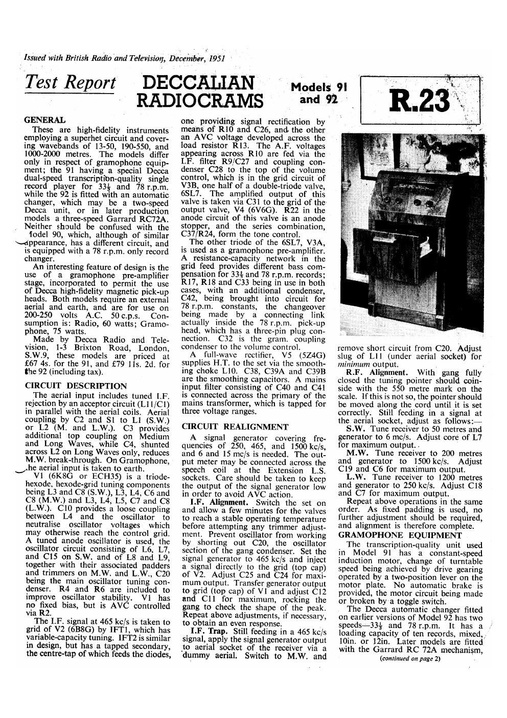
Decca 91 92 service manual

This is the 4 pages manual for decca 91 92 service manual.
Read or download the pdf for free. If you want to contribute, please mail your pdfs to info@audioservicemanuals.com.

Page: 1 / 4
left right
decca 91 92 service manual

Extracted text from decca 91 92 service manual (Ocr-read)


Page 1

Issued with British Main 'and Television, Deceinber, 1951

Test Report

GENERAL

These are high-fidelity instruments
employing a superhet circuit and cover-
ing wavebands of 13-50, 190-550, and
1000-2000 metres. The models difier
only in respect of gramophone equip-
ment; the 91 having a special Decca
dual-speed transcription-quality single
record player for 33%- and 78 r.p.m.
while the 92 is fitted with an automatic
changer, which may be a two-speed
Decca unit, or in later production
models a three-speed Garrard RC72A.
Neither should be confused with the

Iodel 90, which, although of similar

\4ppearance, has a different circuit, and

is equipped with a 78 r.p.m. only record
changer.

An interesting feature of design is the
use of a gramophone pre-amplifier
stage, incorporated to permit the use
of Decca high-fidelity magnetic pick-up
heads. Both models require an external
aerial and earth, and are for use on
200-250 volts A.C. 50 c.p.s. Con-
sumption is: Radio, 60 watts; Gramo-
phone, 75 watts.

Made by Decca Radio and Tele-
vision, 1-3 Brixton Road, London,
S.W.9, these models are priced at
£67 45. for the 91, and £79 lls. 2d. for
the 92 (including tax).

CIRCUIT DESCRIPTION

The aerial input includes tuned I.F.
rejection by an acceptor circuit (L1 l/Cl)
in parallel with the aerial coils. Aerial
coupling by C2 and 81 to L1 (S.W.)
or L2 (M. and L.W.). C3 provides
additional top coupling on Medium
and Long Waves, while C4, shunted
across L2 on Long Waves only, reduces
M.W. breakthrough. On Gramophone,
he aerial input is taken to earth.

V1 (6KSG or ECH35) is a triode-
hexode, hexode-grid tuning components
being L3 and C8 (S.W.), L3, L4, C6 and
C8 (M.W.) and L3, L4, L5, C7 and C8
(L.W.). C10 provides a loose coupling
between L4 and the oscillator to
neutralise oscillator voltages which
may otherwise reach the control grid.
A tuned anode oscillator is used, the
oscillator circuit consisting of L6, L7,
and C15 on S.W. and of L8 and L9,
together with their associated padders
and trimmers on M.W. and L.W., C20
being the main oscillator tuning con-
denser. R4 and R6 are included to
improve oscillator stability. V] has
no fixed bias, but is AVC controlled
via R2.

The I.F. signal at 465 kc/s is taken to
grid of V2 (638G) by lFTl, which has
variable-capacity tuning. IFTZ is similar
in design, but has a tapped secondary,
the centre-tap of which feeds the diodes,

DECCALIAN
RADIOCRAMS

one providing signal rectification by
means of R10 and C26, and. the other
an AVC Voltage developed across the
load resistor R13. The A.F. voltages
appearing across R10 are fed via the
LE filter R9/C27 and coupling con-
denser C28 to the top of the volume
control, which is in the grid circuit 'of
V313, one half of a double-triode valve,
6SL7. The amplified output of this

valve is taken via C31 to the grid of the»

output valve, V4 (6V6G). R22 in the
anode circuit of this valve is an anode
stopper, and the series combination,
C37/R24, form the tone control.

The other triode of the 6SL7, V3A,
is used as a gramophone pre-amplifier.
A resistance-capacity network in the
grid feed provides different bass com-
pensation for 33+ and 78 r.p.m. records;
R17, R18 and C33 being in use in both
cases, with an additional condenser,
C42, being brought into circuit for
78 r.p.m. constants, the changeover
being made by a connecting link
actually inside the 78 r.p.m. pick-up
head, which has a three-pin plug con-
nection. C32 is the gram. coupling
condenser to the volume control.

A full-wave rectifier, V5 (5Z4G)
supplies H.T. to the set via the smooth-
ing choke L10. C38, C39A and C39B
are the smoothing capacitors. A mains
input filter consisting of C40 and C41
is connected across the primary of the
mains transformer, which is tapped for
three voltage ranges.

CIRCUIT REALIGNMENT

A signal generator covering fre-
quencies of 250, 465, and 1500 kc/s,
and 6 and 15 mc/s is needed. The out-
put meter may be connected across the
speech coil at the Extension LS.
sockets. Care should be taken to keep
the output of the signal generator low
in order to avoid AVC action.

I.F. Alignment. Switch the set on
and allow a few minutes for the valves
to reach a stable operating temperature
before attempting any trimmer adjust-
ment. Prevent oscillator from working
by shorting out C20, the oscillator
section of the gang condenser. Set the
signal generator to 465 kc/s and inject
a signal directly to the grid (top cap)
of V2. Adjust C25 and C24 for maxi~
mum output. Transfer generator output
to grid (top cap) of V1 and adjust C12
and C11 for maximum, rocking the
gang to check the shape of the peak.
Repeat above adjustments, if necessary,
to obtain an even response.

I.F. Trap. Still feeding in a 465 kc/s
signal, apply the signal generator output

.to aerial socket of the receiver via a

dummy aerial. Switch to M.W. and

Models 9|
and 92 _

w.

remove short circuit from C20. Adjust
slug of LI] (under aerial socket) for
minimum output. .

R.F. Alignment. With gang fully
closed the tuning pointer should coin-
sidc with the 550 metre mark on the
scale. If this is not so, the pointer should
be moved along the cord until it is set
correctly. Still feeding in a signal at
the aerial socket, adjust as follows:~

S.W. Tune receiver to 50 metres and
generator to 6 mc/s. Adjust core of L7
for maximum output. .

M.W. Tune receiver to 200 metres
and generator to 1500 kc/s. Adjust
C19 and C6 for maximum output.

L.W. Tune receiver to 1200 metres
and generator to 250 kc/s. Adjust C18
and C7 for maximum output.

Repeat above operations in the same
order. As fixed padding is used, no
further adjustment should be required,
and alignment is therefore complete.
GRAMOPHONE EQUIPMENT

The transcription-quality unit used
in Model 91 has a constant-speed
induction motor, change of turntable
speed being achieved by drive gearing
operated by a two-position lever on the
motor plate. No automatic brake is
provided, the motor circuit being made
or broken by a toggle switch.

The Decca automatic changer fitted
on earlier versions of Model 92 has two
speeds-33% and 78 r.p.m.
loading capacity of ten records, mixed.,.
10in. or 12in. Later models are fitted
with the Garrard RC 72A mechanism,

(continued on page 2)

]t has a