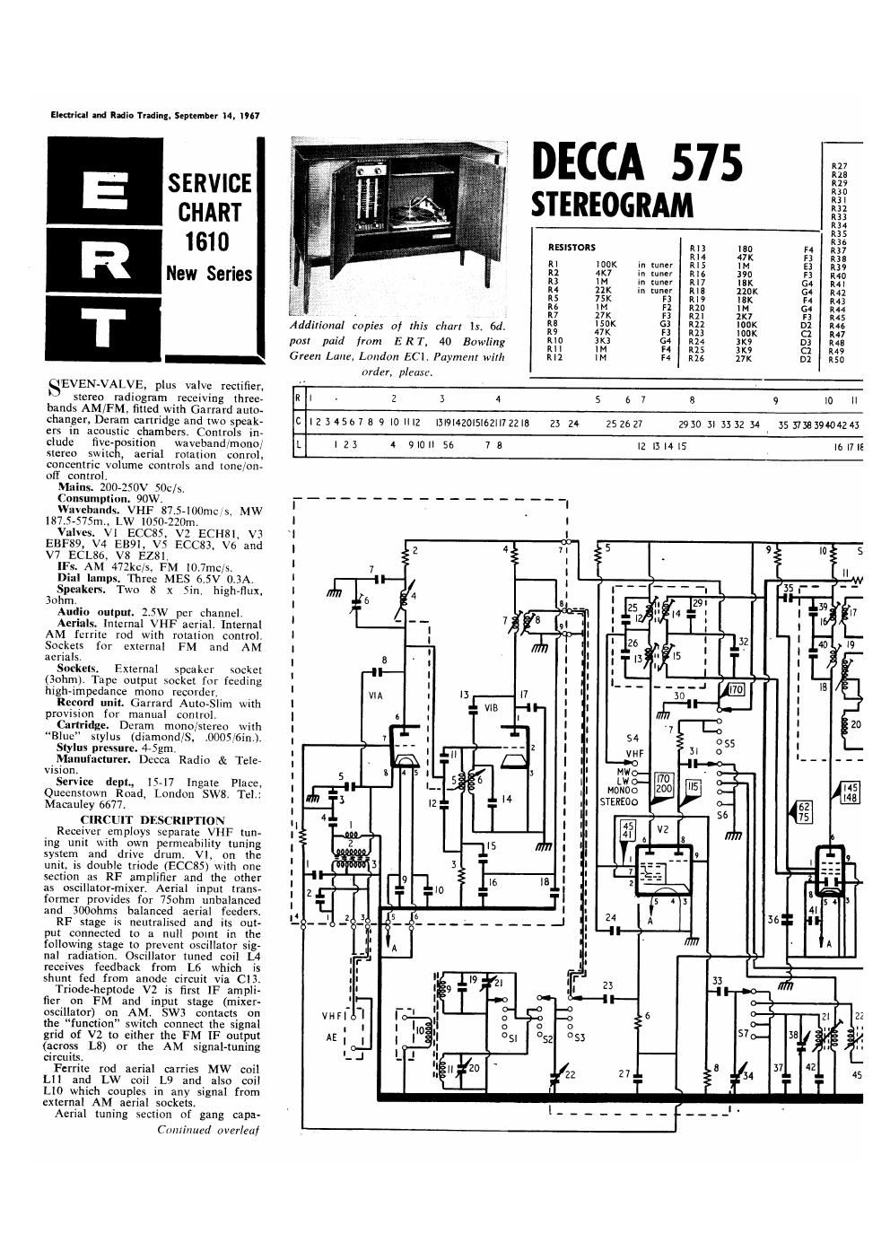
Decca 575 service manual

This is the 4 pages manual for decca 575 service manual.
Read or download the pdf for free. If you want to contribute, please mail your pdfs to info@audioservicemanuals.com.

Page: 1 / 4
left right
decca 575 service manual

Extracted text from decca 575 service manual (Ocr-read)


Page 1

Electrial and Radio Trading. September I4; 1967

SERVICE
CHART
1610

New Series

T

\i'EVEhLVALVE, plus valve rectifier.

stereo radiogram receiving three-
bands AM/FM, fitted with Garrard au10<
changer, Deram cartridge and two speak-
ers in acoustic chambers. Controls in-
clude five- osition wavebandimono/
stereo swiic, aerial rotation conrol,
concentric volume controls and toner/on-
oif control.

Mains. 200-250V SOC/S.

Consumption. 90W.

Waveliands. VHF 87.5400ch5. MW
lS7,5-575m., LW 1050-220m.

Valves. Vl ECCXS. V2 ECHSI. V3
EBF89, V4 E891, V5 ECC83. V6 and
V7 ECL86, V8 E281.

IFS. AM 472kc/s. FM l0.7mc/s.

Dial lamps. Three MES 65V 0,3A.

Speakers. Two 8 x Sin. high-flux.
3ohm,

Audio oulput. 2.5W per channel.
Aerials. Internal VHF aerial. Internal
AM ferrite rod with rotation control.

Sockets for external FM and AM
acrials.
Sockets. External speaker socket

(Bohm). Tape output socket for [ceding
high-impedance mono recorder.

Record unit. Garrard Auto-Slim with
provision for manual control.

Cai1ridge. Deram mono/stereo with
Blue stylus (diamond/S, DOGS/fin).

Stylus pressure. 4-5gm.

Manufacturer. Decca Radio & Tele-
vision.

Service dept., 15-17 lngate Place,
Quecnstown Road, London SW8. Tel:
Macauley 6677,

CIRCUIT DESCRIPTION

Receiver employs separate VHF tun-
ing unit With own permeability tuning
system and drive drum. VI, on the
unit, is double trinde (ECCSS) with one
section as RF amplifier and the other
as oscillator-mixer, Aerial input trans-
former provides for 750hni unbalanced
and 3000th balanced aerial feeders

RF stage is neutralised and its out-
put connectcd to a null point in the
following stage to prevent oscillator sig-
nal radiation. Oscillator tuned coil L4
receives feedback from L6 which is
shunt fed from anode circuit via Cl}.

Triode-heptode V2 is first IF ampli-
fier on FM and input stage (mixer-
oscillator) on AM. SW3 contacts on
the function" switch connect the signal
grid of V2 to either the PM W output
(across L8) or the AM signal-tuning
circuits.

Ferrite rod aerial carries MW coil
L11 and LW coil L9 and also corl
L10 which couples in any signal from
external AM aerial sockets.

Aerial tuning section of gang capa-

Cmiliiiued overleaf

DECCA 575

R27

R15

R29

R30

R3l

I32

R33

R34

R35

R36

RESISTORS RIB I80 F4 R37

RM 47K I3 R38

RI lUOK in tuner R15 4 E3 R39

R2 4K7 in tuner R16 390 F3 INC

513 H4 in (Liner R17 K 54 R

R4 21K in tuner RIG 210K G4 R42

R5 75K F3 RI? [SK 4 R43

R5 4 F2 R10 "4 G4 R44

if; 1231 £3 ii We 5% 5
. . . , . i we
Additional copies of this chart ls. 6d. R9 37$ (E3 M3 $309K 3-; it;

' ' IUD R14 4
pas! paid from E R T, 40 Bowling II In F4 R25 3K9 C1 R49
Green Lane, London EC1. Payment wilh Rll 4 F4 R15 17" DZ 50

order, pleura
R I - 2 3 4 5 6 7 8 9 l0 ll
C l2 345177 8 9 IO |||2 l3l9l420l5l62||722|8 23 24 252627 2930 II 33 32 34 35 37383904243
l. I23 4 9|0||56 7B lZ|3l4|5 |6|7|E