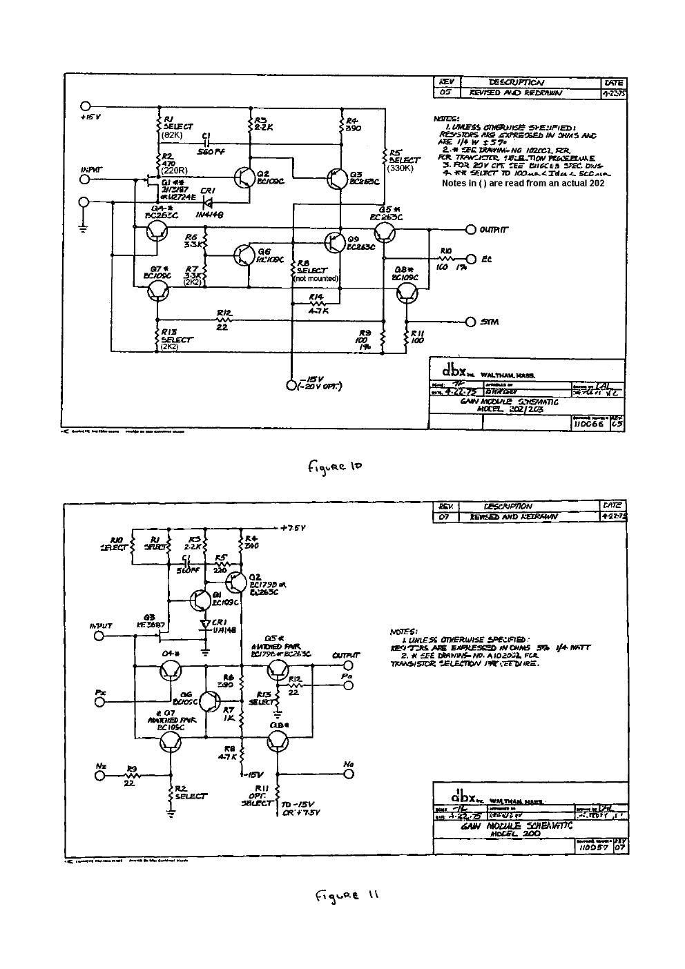
Dbx 202 schematic

This is the 10 pages manual for dbx 202 schematic.
Read or download the pdf for free. If you want to contribute, please mail your pdfs to info@audioservicemanuals.com.

Page: 1 / 10
left right
dbx 202 schematic

Extracted text from dbx 202 schematic (Ocr-read)


Page 2

new-i 45v. um awn. Vi-vv-V-a .,

Re: 202x vs. 202C

The 202): and 202C VCAs are similar in performance and Identical in pin
configuration The main differences between the 202x and 202C are in the -
input and output impedances used (the 202x uses much lower impedancesl.
Further, there is an Internal input Impedance in the 202x of I.2$ko, so the
Input and output resistors must be skewed by I.25I< to keep the m.
gain 0GB with 0V at the control part (When Ec-Ov, the m1 gain is OdB). '

Another difference is in the control-port lmpedances. if the VCAs are
controlled by means of an onamp tied directly to the control port, this will
not matter. However, if a resistor is inserted in serieswith the control
port toscaie the control voltages, it will need to be Changed.

A minor change Is in the resistor feeding the symmetry pin (200k in the
202x, and m in the 2026). Finallyth 202x consumes more power than
the 202C (301M vs about 5 mA), and it may run warmer as a result.

0n the following page. you will find typical circuits for the two VCAs.

Regarding the mad 20m. the circuit diagram for the 202x will
continue to apply. The only difference will be In dc offset at large
attenuation factors. When the 202X is turned off to beyond - I OOdB. there
is the possibility of a dc offset of several millivolts. This will not be the .
case for the 202XL. The new VCA should shut off to -120dB without any
difficulty (although there may oemore than - i 2005 of leakage on the pc
board itself). [Note that the 202C was originally specified to attenuate
down to - l OOdBJ

If you have more questions that are not answered here, please fax again.

Regards,
Bil i Al Ion