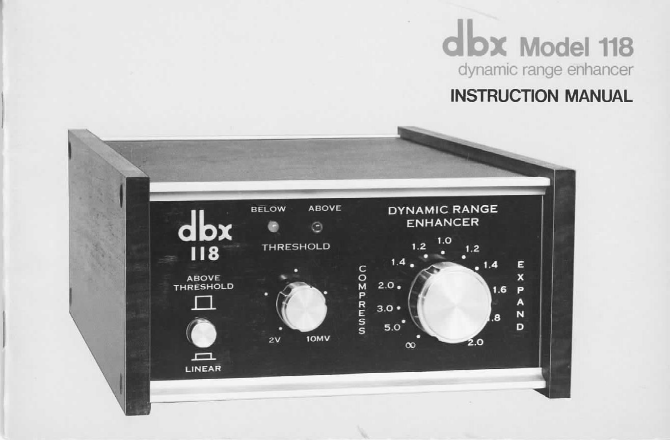
DBX 118 Owners Manual

This is the 35 pages manual for DBX 118 Owners Manual.
Read or download the pdf for free. If you want to contribute, please mail your pdfs to info@audioservicemanuals.com.

Page: 1 / 35
left right
DBX 118 Owners Manual

Extracted text from DBX 118 Owners Manual (Ocr-read)


Page 2

INDEX

BRIEF OPERATING INSTRUCTIONS 2
INTRODUCTION 5
Dynamic Range and Why it is Important 5
dbx Expansion 6
DETAILED OPERATING INSTRUCTIONS/GENERAL NOTES 6
CONNECTIONS 7
OPERATION 15
When to Use Expansion 15
How to Use the 118 as an Expander (Linear Expansion) 15
When to Use Compression 16
How to Use the 118 as a Compressor (Linear Compression) 16
When to Use Peak Unlimiting 17
How to Use the 118 as 3 Peak Unlimiter/Peak Limiter 17
Mono Operation 17
Quad Operation 17
Using the 118 with a Tape Noise Reduction System 18
When to Use dbx Tape Noise Reduction Plus Expansion 18
How to Record and Playback with Expansion 18
When to Record and Playback dbx-Encoded Tapes with Compression 18
How to Peak Limit After Decoding a dbx»Encoded Program 19
COMPRESSORS, LIMITERS AND EXPANDERS, A SUMMARV 19
Compressor 19
Peak Limiter 19
Expander 19
Peak Unlimiler 21
How the 118's Compression/Expansion Circuits Work 2]
SIMPLE PRECAUTIONS WHEN USING ANY PROGRAM EXPANDER 22
SPECIFICATIONS 23
dbx PRODUCT WARRANTY 24
FACTORY SERVICE 24
SCHEMATIC 25
GLOSSARY |

WARNING: TO PREVENT FIRE 0R SHOCK HAZARD.

IN) NO'I' EXPOSE TIIIS APPLIANCE 'IO RAIN OR MOIS'IUHIE.

Page 22

118 increases gain only above the threshold point and does
not act on levels below the threshold point.

Peak Unlimiter

A peak unlimiter is an expander with a high expansion
ratio such as 1:1.4 to 1:1.6 (settings of 1.4 to 1.6 on the
COMPRESS/EXPAND control) which is used to counteract
the effects of peak limiting described earlier. Although
the 118 works best with moderate expansion ratios while
in the LINEAR mode, HIGH EXPANSION RA TIOS
WOULD NORMALLY BE USED TO PROVIDE PEAK
UNLiMlTlNG lN THE ABOVE THRESHOLD MODE.

How the 118's Compression/Expansion Circuits Work

An expander or compressor is made by combining two
devices. One device changes the level of the audio (by
changing its own gain), and the other senses the audio level
to control the gain change device. The 118 uses VCA's
(voltage controlled amplifiers) as the level changing devices.
The 118s VCA gain is linearly proportional, in dB, to the
controlling voltage from the level sensing device. The 118's
level sensing devices respond to the RMS (root-mean-
square) value of the sum of the stereo Input signals, con»
vetting that RMS value to a DC (direct current) control
voltage, which changes in proportion to the dB change of
input signal. Depending on the setting of the COMPRESS/
EXPAND control (i.e. compress or expand) the polarity
of the control voltage is reversed (to plus or minus), and
the fraction of a volt per dB of level change is varied.

The control voltage from the level sensing device is fed to
the VGA where it modifies the audio level appearing at
the 118's outputs.

RMS level sensing is used, rather than peak or simple
average sensing, for several reasons. First. the human ear
and brain perceive loudness in a way that more closely
follows the RMS value than any other value. Thus, when the

118 expands or compresses, it does so on the same basis the
human ear uses to determine loudness. In contrast, a peak
sensing system would respond to short term transients that
do not contribute to loudness and can lead to audible
distortion. RMS level sensing results in very natural changes
in level. dhx uses their own, patented voltage controlled
amplifiers and RMS detectors that work over a wider
dynamic range and have lower noise than any other such
devices available.

A particularly interesting feature of linear decibel com-
pression and expansion is that it works evenly over the
entire dynamic range at all times, regardless of level. This
means that the gain changes are very gradual, spread evenly
over the dynamic spectrum. Competative systems which
concentrate gain changes only at the louder or quieter ends
of the dynamic range must, necessarily, cram a lot of gain
change into a small area. Obviously natural sounding audio
quality cannot benefit from such processing. Furthermore,
the use of a threshold type system necessitates tricky com.
pression/expansion adjustment that would require repeated
attention with almost every new program. The linearity of
the dbx system means such matching is unnecessary.

The peak unlimiting capability (or peak limiting capa-
bility) of the 118 is a special purpose feature. When the 118
is in the ABOVE THRESHOLD mode, it operates by
"ignoring" all signals below the preset THRESHOLD level
(set by the THRESHOLD control). Above that level, the
compression or expansion works just the same as when the
118 is in its LINEAR mode.

21

Page 28

or sound pressure ratio.) if the number of "dB s are referenced to
a given level, than the value of the dB number becomes specific.

dBv expresses a voltage ratio. OdEv is usually referenced
to 0.775V rms. Thus, 0dBv-0.775V, +6dBw1.55V
(twice OdBvl, +20dBv=7.76V (ten times OdBvl. etc.

dBV expresses a voltage ratio and Is similar to dBv, but
OdBV is usually referenced to 1V rms. Thus, OdBV is 2.2dB
higher than OdBv.

dB SPL expresses a Sound Pressure Level ratio. dB SPL Is a
maasure of acoustic pressure (loudness), not acoustic power,
which would be measured in acoustic watts. OdB SPL is

equal to 0.0002 dynes/souare centimeter (the threshold of
human hearing at 1kHzl. As with dBV, an increase of MB SPL
is twit: the sound pressure. and an increase of 20dB SPL

is an increase of 10 times the sound pressure.

dam expresses a power ratio. OdBm is 1 miliiwall (.001
watts), or 0.775V rms delivered to a GOO-ohm load. +3
dBrn=2 milliwatts, or 1.55V into 600 ohms (twice Odflm),
+10dBm-1O milllwatts, or 7.75V into 600 ohms (ten
times DdBm), etc. dBV and dBm are numerically equal
when dealing with EGO-ohm circuits. However, when the
impedance is other than 600 ohms. the value of dBV
remains the same if the voltage is the same, whereas the
value of dBrn decrease; with increasing impedance.

dB alone, without any suffix, doesn't mean anything
unless it is associated with a reference. It may express the
difference between two levels. Thus, the difference
between 1DdBV and 15dBV, the difference between
OdBm and EdBm, and the difference between QOdB SPL
and 95dB SPL are all differences of SdB.

Decay Tlma

Decay time may mean different things, depending on the con-
text. A compressor's decay time is also known as its release time
or recovery time, Alter a Compressor (or expander) changes its
gain to accommodate an incoming signal, and the signal is then
removed, the decay time is the amount of time required for the
circuitry to return to "normal." More precisely, the decay time
is the interval (usually measured In rmcroseoondsl during which
the compressing or expanding amplifier returns to 90% of the
normal gain. Very fast demy times can cause "pumping" or

"breathing" effects, whereas very slow decay times may muse
moderate-level program which follows high-level program or pro-
gram peaks to be too low in level.

Decoder

When a circuit restores an original program from a specially
treated version of that program, the circuit may be said to decode
the program. The equipment or circuit which performs this
function is known as a decoder. Decoders must be used only with
programs which have been enmded by complementary encoding
circuitry. Typical decoders include: FM tuners that use multiplex
decoders to extract left and right stereo signals from left-plus-right
and Ieft-minuwight signals, matrix quadrephonlc decoders that
extract four channels of program from the stereo program on
encoded recordings, and dbx decoders that retrieve wide-dynamic
ranga programs from the compressed programs on obit-encoded
recordings.

De-emphasls It Prremphasis

Deemphasis and ore-emphasis are related processes that are
usually done to avoid audio noise in some storage or transmission
medium. Preemphasls is a boost at specific higher frequencies, the
encoding part of an encoding/decoding system. De-emphasis is an
attenuation at the some frequencies, a reciprocal decoding that
counteracts the preemphasis. In dbx noise reduction, deemphasis
is performed by the decoder lthe play circuitry). The de-emphasis
attenuates high frequencies, thereby reducing tape modulation
noise and restoring the original frequency response of the program
before it was dbx encoded. There are other types of preemphasls
and dis-emphasis. For example, in FM tuners, daamphasis is used
to compensate for special equalization (known as 75-microsecond
Dre-emphasis) applied at the stations transmitter.

Dynamic Range

The dynamic range of a program is the range of signal levels
from the lowest to the highest leveL In equipment, the dynamic
range is the "space," in dB, between the residual noise level and
the maximum undistorted signal level. A program with wide
dynamic range has a large variation from the softest to the loudest
passages, and will tend to be more lifelike than programs with
narrow dynamic range.

Encoder
When a circuit processes an original program to create a
specially treated version of that program, the circuit may be and