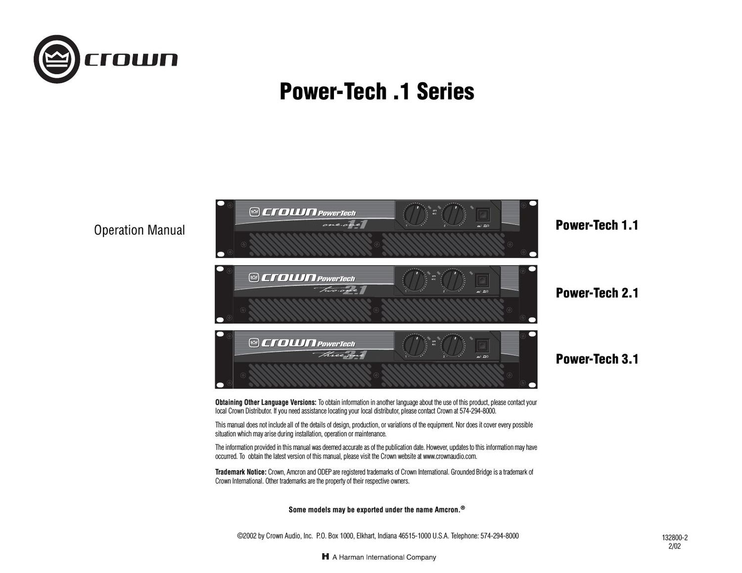
Crown Power Tech 1 Series Owners Manual

This is the 24 pages manual for Crown Power Tech 1 Series Owners Manual.
Read or download the pdf for free. If you want to contribute, please mail your pdfs to info@audioservicemanuals.com.

Page: 1 / 24
left right
Crown Power Tech 1 Series Owners Manual

Extracted text from Crown Power Tech 1 Series Owners Manual (Ocr-read)


Page 1

Power-Tech .1 Series Power Amplifiers page 2Operation Manual Important Safety Instructions 1) Read these instructions. 2) Keep these instructions. 3) Heed all warnings. 4) Follow all instructions. 5) Do not use this apparatus near water. 6) Clean only with a dry cloth. 7) Do not block any ventilation openings. Install in accordance with the manufacturers instruc- tions. 8) Do not install near any heat sources such as radiators, heat registers, stoves, or other apparatus that produce heat. 9) Do not defeat the safety purpose of the polar- ized or grounding-type plug. A polarized plug has two blades with one wider than the other. A grounding-type plug has two blades and a third grounding prong. The wide blade or the third prong is provided for your safety. If the provided plug does not fit into your outlet, consult an electrician for replacement of the obsolete outlet. 10) Protect the power cord from being walked on or pinched, particularly at plugs, convenience receptacles, and the point where they exit from the apparatus. 11) Only use attachments/accessories specified by the manufacturer. 12) Use only with a cart, stand, bracket, or table specified by the manufacturer, or sold with the apparatus. When a cart is used, use caution when moving the cart/apparatus combination to avoid injury from tip-over. 13) Unplug this apparatus during lightning storms or when unused for long periods of time. 14) Refer all servicing to qualified service person- nel. Servicing is required when the apparatus has been damaged in any way, such as power- supply cord or plug is damaged, liquid has been spilled or objects have fallen into the apparatus, the apparatus has been exposed to rain or moisture, does not operate normally, or has been dropped. 15) To reduce the risk of fire or electric shock, do not expose this apparatus to rain or moisture.TO PREVENT ELECTRIC SHOCK DO NOT REMOVE TOP OR BOTTOM COVERS. NO USER SERVICE- ABLE PARTS INSIDE. REFER SERVICING TO QUALIFIED SERVICE PERSONNEL. Ã- PRÉVENIR LE CHOC ÉLECTRIQUE NENLEVEZ PAS LES COUVERCLES. IL NY A PAS DES PAR- TIES SERVICEABLE Ã- LINTÉRIEUR. TOUS REPA- RATIONS DOIT ETRE FAIRE PAR PERSONNEL QUALIFIÉ SEULMENT. IMPORTANT Power-Tech .1 Series amplifiers require Class 2 output wiring. MAGNETIC FIELD CAUTION! Do not locate sensitive high-gain equip- ment such as preamplifiers or tape decks directly above or below the unit. Because this amplifier has a high power density, it has a strong magnetic field which can induce hum into unshielded devices that are located nearby. The field is strongest just above and below the unit. If an equipment rack is used, we recommend locat- ing the amplifier(s) in the bottom of the rack and the preamplifier or other sensitive equipment at the top. WATCH FOR THESE SYMBOLS: The lightning bolt triangle is used to alert the user to the risk of electric shock. The exclamation point triangle is used to alert the user to important operating or maintenance instruc- tions.

Page 2

Power-Tech .1 Series Power Amplifiers page 3 Operation Manual Important Safety Instructions .............................................. 2 Table of Contents ................................................................. 3 1 Welcome ................................................................................... 4 1.1 Features.......................................................................... 4 2 How to Use This Manual ....................................................... 4 3 Setup.......................................................................................... 5 3.1 Unpack Your Amplifier ............................................... 5 3.2 Install Your Amplifier .................................................. 5 3.3 Ensure Proper Cooling ............................................... 5 3.4 Choose Input Wire and Connectors ......................... 6 3.5 Choose Output Wire and Connectors ...................... 7 3.6 Wire Your System ....................................................... 8 3.6.1 Stereo Mode...................................................... 8 3.6.2 Bridge-Mono Mode.......................................... 8 3.6.3 Parallel-Mono Mode......................................... 8 3.7 Set Input Sensitivity .................................................. 9 3.8 Connect to AC Mains .................................................. 9 3.9 Startup Procedure ....................................................... 9 4 Operation ................................................................................. 9 4.1 Precautions .................................................................. 9 4.2 Front Panel Controls and Indicators ......................... 10 4.3 Back Panel Controls and Connectors ............................. 11 5 Advanced Features and Options ......................................... 13 5.1 Protection Systems .................................................... 13 5.1.1. ODEP................................................................. 13 5.1.2 Ultrasonic and Radio Frequency Protection.13 5.1.3 Drive Protection................................................ 13 5.1.4 Transformer Thermal Protection.................... 13 5.1.5 Fuses and Circuit Breakers.............................. 13 5.2 Option ........................................................................... 14 5.2.1 MT-BB................................................................. 14 6 Troubleshooting ...................................................................... 15 7 Specifications ......................................................................... 16 8 Service ..................................................................................... 17 8.1 Worldwide Service ...................................................... 18 8.2 US and Canada Service .............................................. 18 8.2.1 Service at a US or Canada Service Center ............. 18 8.2.2 Factory Service ..................................................... 18 8.2.3 Factory Service Shipping Instructions................... 18 9 Warranty .................................................................................. 19 Factory Service Information Form ........................................... 21 Table of Contents

Page 6

Power-Tech .1 Series Power Amplifiers page 7 Operation Manual 3.5 Choose Output Wire and Con- nectors Crown recommends using pre-built or profes- sionally wired, high-quality, two-conductor, heavy gauge speaker wire. Use bare wire, a dual banana plug or spade lugs on the amplifier end of each speaker cable (Figure 3.5). To prevent the possibility of short-circuits, wrap or other- wise insulate exposed loudspeaker cable con- nectors. Using the guidelines below, select the appropri- ate size of wire based on the distance from amplifier to speaker. CAUTION: Never use shielded cable for output wiring.Distance Wire Size up to 25 ft. 16 gauge 26-40 ft. 14 gauge 41-60 ft. 12 gauge 61-100 ft. 10 gauge 101-150 ft. 8 gauge 151-250 ft. 6 gauge Figure 3.5 Output Connector Wiring 3 Setup